Closed-Loop Scanners
5
Keysight 5500 SPM User’s Guide
5-11
without affecting the agreement of trace and retrace in closed loop
scanning.
28
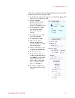
Adjust the X sensor
Sensitivity Ratio:
a
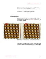
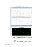
In the Realtime Images window, set up two Topography images,
one for
Trace
and one for
Retrace.
b
Place a vertical cursor at the same location in the Trace and
Retrace images. The cursor should cross the same features in both
images.
c
If this is not the case, adjust the X Sensitivity Ratio and re-scan.
Alignment should be consistent across the full range of the X
axis.
Several iterations may be necessary to align all edges in the
Trace and Retrace images.
29
Adjust the Y sensor
Sensitivity Ratio:
a
In the Realtime Images window, assign one data channel to display a
single frame of the calibration target and place a vertical
cross-section through a line of features. Allow the scanner to scan
continuously, which will update the Cross Section plot each pass
through the frame.
b
Use the upward (trace) and downward (retrace) scan markers to
measure the difference in the acquired data at a given point on the Y
axis. While scanning in one direction, focus on one step of the
grating. As the scan data is plotted, position a marker on this edge.
Wait for the scan in the opposite direction to occur and position a
second marker on the same edge after the plot has been updated.
Alignment of the individual edges should be confirmed across the
full range of the Y axis.
c
If this is not the case, adjust the Y Sensitivity Ratio and re-scan.
Several iterations may be necessary to align all edges in both the
upward and downward scans.
30
Save the Scanner Setup parameters.
Z Sensor Calibration
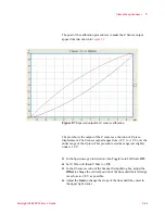
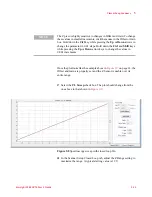
To calibrate the Z sensor, the output of the sensor will be plotted while
the piezo is being moved through its entire range. Since only the motion


