background image

Power Sensor Specifications (Autorange Mode)

Specifications 

Keysight 81630B/4B/6B Power Sensor Modules and Keysight 81635A Dual Power Sensor Module, Edition 4

31

[1]

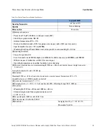
 Reference Conditions

• Power level 80 

μ

W, continuous wave (CW)

• SM  Fiber  9 

μ

m graded-index, NA=0.1

• Ambient temperature 23

°

±

 5

°

C

• On day of calibration (add 

±

 0.3% for ageing over one year; add 

±

 0.6% over two years)

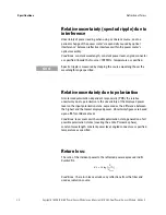
• Spectral width of source < 10 nm (FWHM)

• Wavelength setting at Power Meter must correspond to source wavelength 

±

 0.4 nm

[2]

 Operating Conditions:

• Fiber 

 50 

μ

m, NA 

 0.2

• Connectors with 2.5 mm ferrule with flat face (fiber tip offset not more than 0.3 mm from 2.5 mm cross-

section) with straight or angled polish; see note for Connector Interfaces on page 17 for unspecified use 


of connectors with 1.25 mm ferrules.

• Within one year of calibration, add 0.3% for second year

• Operating temperature as specified, humidity: non-condensing

[3]

 All states of polarization at constant wavelength (1550 nm 

±

 30 nm) and constant power, straight connector, 


T=23

°

C

±

°

C

For angled connector (8

°

) add 

± 

0.01 dB typ.

[4]

 Conditions:

Wavelength 1550 nm 

±

 30 nm, fixed state of polarization, constant power, Temperature 23

°

±

 5

°

C

Linewidth of source 


100 MHz, angled connector 8

°

[5]

 At constant temperature (

Δ

T = 

±

 1

°

C)

[6]

 Averaging time 1 s, T = 23

°

±

 5 

°

C, observation time 300 s. Wavelength range 1255 - 1630 nm.

[7] 

Conditions

• Wavelengths 1310 nm 

±

 30 nm and 1550 nm 

±

 30 nm

• Standard single-mode fiber, angled connector min 8

°

• T=  23

°

±

 5 

°

C

[8] 

For input power > +10 mW add:

typ. ±0.0012 dB/mW

In case of negative power change > 50 dB allow additional recovery time of 3 min.

[9]

 30

°

C for > + 20dBm input power

Keysight 81630B

Summary of Contents for 816304B

Page 1: ...Keysight 81630B 4B 6B Power Sensor Modules and Keysight 81635A Dual Power Sensor Module User s Guide ...

Page 2: ......

Page 3: ......

Page 4: ...r shall prepay shipping charges to Keysight and Keysight shall pay shipping charges to return the product to Buyer However Buyer shall pay all shipping charges duties and taxes for products returned to Keysight from another country Keysight warrants that its software and firmware designated by Keysight for use with an instrument will execute its programming instructions when properly installed on ...

Page 5: ...u can also contact one of the following centers and ask for a test and measurement sales representative United States 1 800 829 4444 1 800 829 4433 FAX Canada 1 877 894 4414 1 800 746 4866 FAX Europe 31 20 547 2111 31 20 547 2190 FAX Japan 120 421 345 120 421 678 FAX Mexico 52 55 5081 9469 52 55 5081 9467 FAX Australia 800 629 485 800 142 134 FAX Asia Pacific 852 800 930 871 852 800 908 476 FAX La...

Page 6: ......

Page 7: ...scription of the Front Panel 13 Analog Output 14 Optical Input 14 Operation 14 Accessories 15 Modules and Options 16 Connector Interfaces 17 Bare Fiber Adapters 18 Specifications 19 Definition of Terms 20 Averaging Time 20 Linearity 21 Linewidth 21 Noise 22 Power range 22 Reference conditions 22 Offset 23 Relative uncertainty spectral ripple due to interference 24 Relative uncertainty due to polar...

Page 8: ...re 35 Instrument Specification 35 Performance Test Procedures 36 Accuracy Test 37 Test Setup 37 Linearity Test 39 Test Setup 39 10 dBm Range 41 0 dBm Range 41 10 dBm Range 42 20 dBm Range 42 30 dBm Range 43 Change Setup 43 40 dBm Range 43 50 dBm Range 44 Calculation 44 Example Measurement Results 45 Calculations 46 Noise Test 48 Return Loss Test 49 Relative Uncertainty due to Polarization Optional...

Page 9: ...ened cleaning wipes 78 Polymer film 78 Infrared Sensor Card 78 Preserving Connectors 79 Cleaning Instrument Housings 80 Which Cleaning Procedure should I use 80 How to clean connectors 81 How to clean connector interfaces 83 How to clean bare fiber adapters 84 How to clean lenses 85 How to clean instruments with a fixed connector interface 86 How to clean instruments with a recessed lens interface...

Page 10: ...8 Keysight 81630B 4B 6B Power Sensor Modules and Keysight 81635A Dual Power Sensor Module Edition 4 ...

Page 11: ...r Modules and the 81635A Dual Power Sensor Module Safety Considerations 10 Safety Symbols 10 Initial Inspection 11 Line Power Requirements 11 Operating Environment 11 Storage and Shipment 11 Environmental Information 12 What is a Power Sensor Module 13 A Description of the Front Panel 13 Analog Output 14 Optical Input 14 ...

Page 12: ... for the customer s failure to comply with these requirements Before operation review the instrument and manual including the red safety page for safety markings and instructions You must follow these to ensure safe operation and to maintain the instrument in safe condition Safety Symbols The apparatus will be marked with this symbol when it is necessary for the user to refer to the instruction ma...

Page 13: ...erate when installed in the 8163A B Lightwave Multimeter 8164A B Lightwave Measurement System and 8166A B Lightwave Multichannel System Operating Environment The safety information in the 8163A B Lightwave Multimeter 8164A B Lightwave Measurement System and 8166A B Lightwave Multichannel System User s Guide summarizes the operating ranges for the Keysight 81630B 4B 6B Power Sensor Modules and Keys...
Page 14: ...affixed label indicates that you must not discard this electrical electronic product in domestic household waste Product Category With reference to the equipment types in the WEEE Directive Annex I this product is classed as a Monitoring and Control instrumentation product Do not dispose in domestic household waste To return unwanted products contact your local Keysight office or see http about ke...

Page 15: ...4 13 What is a Power Sensor Module A Power Sensor Module measures the power emitted from a connected single mode or multi mode fiber with Numerical Aperture 0 24 0 3 and core diameter up to 100 μm according to the model The wavelength and power range depend on the sensor element A Description of the Front Panel Figure 1 Front Panel of the Keysight Power Sensor Modules ...

Page 16: ...the best range for the application using the mainframe user interface Select Menu Range Mode Manual and then choose from the list of ranges Applications Possible applications for the analog output are to close the feedback loop controlling the current supplied to a laser to aid positioning the system for fiber alignment tasks to monitor optical power on an oscilloscope The analog signal reacts ins...

Page 17: ... 81635A Dual Power Sensor Module are available in various configurations for the best possible match to the most common applications This chapter provides information on the available options and accessories Modules and Options 16 Connector Interfaces 17 Bare Fiber Adapters 18 ...

Page 18: ...ies Modules and Options 16 Keysight 81630B 4B 6B Power Sensor Modules and Keysight 81635A Dual Power Sensor Module Edition 4 Modules and Options Figure 2 Recommended Connector Interfaces and Bare Fiber Adapters ...

Page 19: ...s within the tolerances of the connectors and adapters The 81635A and 81636B sensor inputs make an off center contact with the ferrule so the 81000LI and 81000MI which allow physical contact give good positioning repeatability For LC and MU connectors use of the 8162x optical power heads or N7744A and N7745A power meters with corresponding adapters are rec ommended for highest accuracy Ferrules wi...

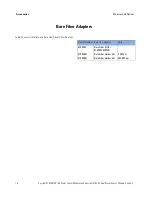
Page 20: ...ight 81635A Dual Power Sensor Module Edition 4 Bare Fiber Adapters Table 2 Connector Interface and Bare Fiber Adapter Combinations Product Number Bare Fiber Adapter Note 81000BI Bare Fiber Kit for 81630B 81634B 81004BH Bare Fiber Holder Set 0 400μm 81009BH Bare Fiber Holder Set 400 900μm ...

Page 21: ...n warranted typical performance Because of the modular nature of the instrument these performance specifications apply to these modules and heads rather than the mainframe unit Definition of Terms 20 Averaging Time 20 Linearity 21 Linewidth 21 Noise 22 Power range 22 Reference conditions 22 Relative uncertainty spectral ripple due to interference 24 Relative uncertainty due to polarization 24 Retu...

Page 22: ...nce Tests on page 33 Generally all specifications apply for the given environmental conditions and after warmup time Measurement principles are indicated Alternative measurement principles of equal value are also acceptable Averaging Time Time defining the period during which the power meter takes readings for averaging At the end of the averaging time the average of the readings is available disp...

Page 23: ...essed in Watts If expressed in If expressed in dB Conditions Reference level 10 μW Power range and range setting as specified Note 1 Ideally Linearity is 0 or 0 dB respectively Note 2 The power dependent nonlinearity N Px can alternatively be expressed by the following formula where r P is the power dependent responsivity for a power meter the responsivity is defined as the ratio of displayed powe...

Page 24: ...et is automatically excluded this way Power range The power range is defined from the highest specified input power level to the smallest input power level that causes a noticable change of displayed power level Conditions wavelength averaging time as specified Reference conditions The specified conditions during the spectral responsivity calibration or conditions which are extrapolated from the c...

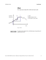
Page 25: ...wer Sensor Modules and Keysight 81635A Dual Power Sensor Module Edition 4 23 Offset The average power reading without incident optical power dark Figure 3 Offset The power meter is adjusted to zero offset by doing a zero operation with darkened power meter NOTE ...

Page 26: ... responsivity PDR the relative uncertainty due to polarization is the uncertainty of the displayed power level on the input polarization state expressed as the difference between the highest and the lowest displayed power Uncertainty figures are based upon a 95 confidence level Conditions laser source with variable polarization state generation of all possible polarization states covering the enti...

Page 27: ...nt temperature re calibration period as specified Noise and drift observed over a specified observation time with a temperature change of not more than ΔT Uncertainty at reference conditions The uncertainty for the specified set of reference conditions including all uncertainties in the calibration chain from the national laboratory to the test meter Wavelength Range The range of wavelengths for w...

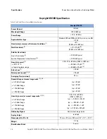
Page 28: ...rence Conditions 1 3 1200 nm to 1630 nm 2 5 1000 nm to 1630 nm Total Uncertainty 2 5 20 pW 8 9 1200 nm to 1630 nm 4 5 0 2 pW 1000 nm to 1630 nm Relative Uncertainty Due to Polarization 3 0 015 dB typical 0 005 dB Spectral Ripple due to interference 4 0 015 dB typical 0 005 dB Linearity power 5 CW 10 to 60 dBm 1200 to 1630 nm CW 10 to 90 dBm 1000 to 1630 nm at 23oC 5oC 0 02 dB 20 pW 9 0 015 dB 0 2 ...

Page 29: ...only for LC connector use 81000LI adapter not 81002LI for MU connector use 81000MI not 81002MI Averaging Time 1s Only 81635A For Fiber 62 5μm graded index NA 0 24 add 2 Within one year of calibration add 0 3 for second year Operating temperature as specified humidity non condensing 3 All states of polarization at constant wavelength 1550 nm 30 nm and constant power straight connector T 23 C 5 C Fo...

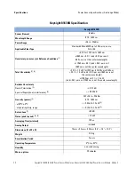
Page 30: ...tral Ripple due to interference 4 0 015 dB typical 0 015 dB typical Linearity power 5 CW 10 to 60 dBm 1260 to 1630 nm at 23oC 5oC 0 02 dB 20 pW 9 at operating temp range 0 06 dB 20 pW 9 Return Loss 7 40 dB Noise peak to peak 5 6 20 pW Averaging Time minimal 25 μs Dynamic Range at manual range mode 5 10 at 10 dBm Range typ 55 dB at 0 dBm Range typ 55 dB at 10 dBm Range typ 52 dB at 20 dBm Range typ...

Page 31: ...0MI not 81002MI Within one year of calibration add 0 3 for second year Operating temperature as specified humidity non condensing 3 All states of polarization at constant wavelength 1550 nm 30 nm and constant power straight connector T 23 C 5 C For angled connector 8 add 0 01 dB typ 4 Conditions Wavelength 1550 nm 30 nm fixed state of polarization constant power Temperature 23 C 5 C Linewidth of s...

Page 32: ... is not the center wavelength Total Uncertainty 2 8 5 0 1 2 nW for 1255 nm to 1630 nm at 980 nm 5 5 1 2 nW add 0 5 per nm if 980 nm is not the center wavelength at 1060 nm 6 0 1 2 nW add 0 6 per nm if 1060 nm is not the center wavelength Relative Uncertainty Due to Polarization 3 0 01 dB Spectral Ripple due to interference 4 0 005 dB Linearity power 5 CW 28 to 50 dBm 970 1630 nm at 23oC 5oC 0 05 d...

Page 33: ...s on page 17 for unspecified use of connectors with 1 25 mm ferrules Within one year of calibration add 0 3 for second year Operating temperature as specified humidity non condensing 3 All states of polarization at constant wavelength 1550 nm 30 nm and constant power straight connector T 23 C 5 C For angled connector 8 add 0 01 dB typ 4 Conditions Wavelength 1550 nm 30 nm fixed state of polarizati...

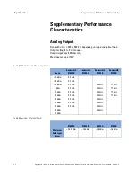
Page 34: ...t impedance 600 ohm typ Max input voltage 10V Table 5 3dB bandwidth of the Analog Output Range Bandwidth 81630B Bandwidth 81635A Bandwidth 81634B Bandwidth 81636B 30 dBm 3 5 kHz 20 dBm 3 5 kHz 10 dBm 3 5 kHz 5 0 kHz 17 kHz 0 dBm 3 5 kHz 5 0 kHz 17 kHz 10 dBm 3 0 kHz 5 0 kHz 17 kHz 20 dBm 3 0 kHz 5 0 kHz 17 kHz 30 dBm 0 3 kHz 4 0 kHz 40 dBm 0 3 kHz 4 0 kHz 50 dBm 0 3 kHz 0 3 kHz 60 dBm 0 3 kHz 70 d...

Page 35: ...rmed without access to the interior of the instrument The performance tests refer specifically to tests using the Diamond HMS 10 Keysight connector Equipment Required 34 Test Record 35 Test Failure 35 Instrument Specification 35 Performance Test Procedures 36 Accuracy Test 37 Linearity Test 39 Example Measurement Results 45 Noise Test 48 Return Loss Test 49 Relative Uncertainty due to Polarization...

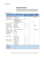
Page 36: ...eysight 81618A Optical Head Interface Module with Keysight 81624B C01 Working Standard Optical Head x x x x Power Sensor Module Keysight 81634B x x x x Optical Attenuator 8156A 221 x x x x Optical Attenuator 8156A 101 x x x x 81560A Return Loss Module Keysight 81613A x x x x Return Loss Reference Cable Keysight 81610CC x x x x Tunable Laser Source 8164A B and 81680A 022 o o 8168E F 022 Polarizatio...

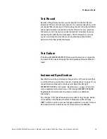
Page 37: ... Failure If the Keysight 81630B 4B 5B 6B fails any performance test return the instrument to the nearest Keysight TechnologiesSales Service Office for repair Instrument Specification Specifications are the performance characteristics of the instrument that is certified These specifications listed in Specifications on page 19 are the performance standards or limits against which the Keysight 81630B...
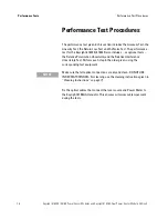
Page 38: ...ht 81630B 81634B also includes as optional tests the Relative Polarization Uncertainty and the Relative Interference Uncertainty Test Perform each step in the order given using the corresponding test equipment Fix the optical cables that connect the laser source and Power Meter to the Keysight 8156A Attenuator This ensures minimum cable movement during the tests Make sure that all optical connecti...

Page 39: ...e to the head or to the DUT 3 Move to the Laser Source channel move to the wavelength parameter λ press Enter select the lower wavelength source and press Enter 4 If you are using a Keysight 81657A Laser Source ensure that you initialize the Keysight 8156A Optical Attenuator with 30 dB attenuation Figure 4 Accuracy Test Setup 5 Turn the instruments on enable the laser source and allow the instrume...

Page 40: ...nput of the Device Under Test DUT 8163xA is not receiving any light by placing a plastic cap over the input Move to the DUT Power Meter channel press Menu move to Zero press Enter 8 Ensure that the Keysight 8156A output is disabled Move to the reference Power Meter channel 81624B 81618A press Menu move to Zero press Enter 9 Enable the Keysight 8156A output and change the attenuation until the refe...

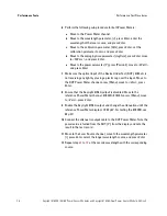
Page 41: ...Disable both attenuators and enable the laser source where the source wavelength is chosen to 1550 nm If you are using the 81657A move to the wavelength parameter λ press Enter select the longer wavelength source 1550 nm nominally and press Enter 4 Set the wavelength of both attenuators to the same wavelength as the laser source 5 Perform the following sub procedure for both Power Meters a Move to...

Page 42: ...ttenuation of the 8156A 221 with Monitor Output referred to as Atty1 to 0 dB b Set the attenuation of the other 8156A referred to as Atty2 to 45 dB 7 Wait at least 15 minutes until the laser source is stabilized 8 Perform the following sub procedure for the reference Power Meter 81634B a Press Menu move to Range mode move to Manual and press Enter b Move to Range press Enter move to 50 dBm press E...

Page 43: ...orm the following sub procedure for the DUT 8163xA B a Press Menu move to Range mode move to Manual and press Enter b Move to Range press Enter move to 0 dBm and press Enter 17 If necessary adjust the attenuation of Atty2 in order to be on the upper limit of the 50 dBm range i e 47 2 dBm 0 dBm Range 18 Disable Atty1 19 Zero both Power Meters On the 8163A B with two installed power meters press Men...

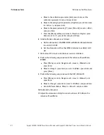
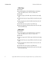
Page 44: ...the test record 8 34 On the DUT switch one range down to the 20 dBm range 35 Decrease the attenuation of Atty2 by 10 dB in order to be on the upper limit of the 50 dBm range 20 dBm Range 36 Disable Atty1 37 Zero both Power Meters On the 8163A B with two installed power meters press Menu move to Zero all and press Enter 38 Enable Atty1 39 Switch one range up to the 10 dBm range and note the power r...

Page 45: ...e output with the monitor output 52 Set the attenuation of Atty1 to 35 dB and of Atty2 to 25 dB 53 Enable Atty1 again 54 Adjust the attenuation of both attenuators in the following order Atty1 DUT Power Meter shows a reading of 37 2 dBm and Atty2 the REF Power Meter shows a reading of 47 2 dBm 40 dBm Range 55 Disable Atty1 56 Zero both Power Meters On the 8163A B with two installed power meters pr...

Page 46: ...163A B with two installed power meters press Menu move to Zero all and press Enter 65 Enable Atty1 66 Switch one range up to the 40 dBm range and note the power readings 18 67 Switch one range down 50 dBm and note the power readings 19 68 Increase the attenuation of Atty1 by 10 dB and note the results in the test record 20 Calculation 69 Calculate the non linearity using the formulas given in the ...

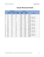
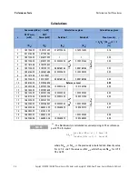
Page 47: ... 23 1 0 47 196 7 164 RangeDisc lower limit 7 17 4 23 1 10 47 197 7 165 RangeDisc upper limit 8 27 4 23 1 10 57 186 17 155 InRange 9 27 4 13 1 10 47 196 17 155 RangeDisc lower limit 10 27 4 13 1 20 47 197 17 156 RangeDisc upper limit 11 37 4 13 1 20 57 201 27 162 InRange 12 37 4 3 1 20 47 208 27 161 RangeDisc lower limit 13 37 4 3 1 30 47 209 27 162 RangeDisc upper limit 14 47 4 3 1 30 57 213 37 16...

Page 48: ...722E 05 0 01925307 0 999769768 0 999769768 0 00 10 1 90678E 05 0 019248638 Reference Level 0 00 11 1 90502E 06 0 001922206 10 00921458 R n 1 R n 10 01382506 D n D n 1 0 05 12 1 90195E 05 0 001922649 13 1 90152E 05 0 001922206 1 000230285 1 000230285 0 05 14 1 89977E 06 0 000192044 10 00921458 10 00921458 0 05 15 1 86552E 05 0 000187025 16 1 86509E 05 0 000186982 1 000230285 1 000230285 0 05 17 1 8...

Page 49: ...Performance Test Procedures Performance Tests Keysight 81630B 4B 6B Power Sensor Modules and Keysight 81635A Dual Power Sensor Module Edition 4 47 Figure 6 Linearity Test ...

Page 50: ...nter The Stability Setup Screen appears 3 Ensure that the correct channel is selected in the upcoming Module Selection box 4 Press Menu to access the Logging application menu screen 5 Move to Pwr unit press Enter move to W and press Enter 6 Move to AvgTime press Enter move to 1 s and press Enter 7 Move to Range mode press Enter move to Auto and press Enter and press Close 8 Press the Parameter sof...

Page 51: ...ilize 6 At the Power Meter a Set the averaging time AvTime to 1s To ensure traceability use the 81610CC Reference Cable for calibration measurements Do not use the 81610CC Reference Cable for measurements on a Device Under Test Instead use a measurement patchcord NOTE It is important to maintain the quality of the straight connector end of the 81610CC Reference Cable Never add another connector to...

Page 52: ...8 At the Power Meter press Disp Ref The Power Meter should now read 0 0 dB 9 Disconnect the 81610CC Reference Cable from the setup and connect a 81113SC user cable to the Return Loss Module and leave the other end open as shown in Figure 8 Figure 8 Return Loss Measurement Setup 10 At the Return Loss Module press TermCal in order to calibrate the Return Loss Module at termination condition 11 Conne...

Page 53: ...unchanged by normal use of the sensor module Below you will find the test setup to verify the relative uncertainty due to polarization of the sensor module Generally during this measurement procedure the tunable laser source is swept through a predefined wavelength range After every wavelength step a single PDL measurement is made where the polarization controller generates all different polarizat...

Page 54: ...Performance Tests Performance Test Procedures 52 Keysight 81630B 4B 6B Power Sensor Modules and Keysight 81635A Dual Power Sensor Module Edition 4 Figure 9 Measurement Setup for PDL Test ...

Page 55: ...ainty due to interference test it is mandatory to use two mainframes since the time difference between measurement A und B for a specific wavelength point has to be at most 2 ms Due to this short measurement interval the performance test of the relative uncertainty due to interference can only be using computer control The performance test Relative Uncertainty due to Interference is optional since...

Page 56: ...wer Sensor Module Edition 4 Figure 10 Setup for Relative Uncertainty due to Interference Measurement Theoretically both Power Meters are monitoring the power ratio over the variable wavelength in a predefined range as shown in Figure 11 Ensure that the tunable laser source is mode hop free in the tested wavelength range ...

Page 57: ...Performance Test Procedures Performance Tests Keysight 81630B 4B 6B Power Sensor Modules and Keysight 81635A Dual Power Sensor Module Edition 4 55 Figure 11 Interference Ripple ...
Page 58: ..._________ Customer _________________________ Performed by _________________________ Report No _________________________ Special Notes ______________________________________________________________________ ______________________________________________________________________ ______________________________________________________________________ _____________________________________________________...

Page 59: ..._____ ___________ 3b Optical Head Reference 81624B ____________ ___________ 4 Sensor Module 81630B ____________ ___________ 5a Optical Attenuator 8156A 221 ____________ ___________ 5b Optical Attenuator 8156A 101 ____________ ___________ 6 Return Loss Module 81613A ____________ ___________ 79 ____________________________ ____________ ____________ ___________ 8 ____________________________ ________...

Page 60: ... want to use the appropriate sheet Range PDUT dBm PDUT dBm Loss 20 10 ________ _______ 1 241 10 10 ________ _______ 1 16 10 3 ________ _______ 1 16 0 3 ________ _______ 1 16 0 7 ________ _______ 1 16 10 7 ________ _______ 1 16 10 17 ________ _______ 1 17 20 17 Reference 0 0 1 17 20 27 ________ _______ 1 22 30 27 ________ _______ 1 22 30 37 ________ _______ 1 76 40 37 ________ _______ 1 76 40 47 __...

Page 61: ...e as used here to check this functionality The non linearity of the 81630B is not regularly tested up to the specified power level of 28 dBm Instead limited testing up to 10 dBm is used to test the electronic circuitry and diode of the 81630B Above 10 dBm the largest contribution to non linearity comes from the absorbing glass filter that does not change its non linearity with time This way it is ...

Page 62: ...Customer _________________________ Performed by _________________________ Report No _________________________ Special Notes ______________________________________________________________________ ______________________________________________________________________ ______________________________________________________________________ _______________________________________________________________...

Page 63: ...ysight 81618A ____________ 3b Optical Head Reference Keysight 81624B ____________ 4 Sensor Module Keysight 81634B ____________ 5a Optical Attenuator 8156A 221 ____________ 5b Optical Attenuator 8156A 101 ____________ 6 Return Loss Module Keysight 81613A ____________ 7 ____________________________ ____________ ____________ 8 ____________________________ ____________ ____________ 9 _________________...

Page 64: ...se the appropriate sheet Range PDUT dBm PDUT dBm Loss 10 9 ________ _______ 0 35 10 3 ________ _______ 0 35 0 3 ________ _______ 0 35 0 7 ________ _______ 0 35 10 7 ________ _______ 0 35 10 17 ________ _______ 0 35 20 17 Reference 0 0 0 35 20 27 ________ _______ 0 35 30 27 ________ _______ 0 35 30 37 ________ _______ 0 35 40 37 ________ _______ 0 35 40 47 ________ _______ 0 35 50 47 ________ _____...

Page 65: ...Customer _________________________ Performed by _________________________ Report No _________________________ Special Notes ______________________________________________________________________ ______________________________________________________________________ ______________________________________________________________________ _______________________________________________________________...

Page 66: ...ysight 81618A ____________ 3b Optical Head Reference Keysight 81624B ____________ 4 Sensor Module Keysight 81634B ____________ 5a Optical Attenuator 8156A 221 ____________ 5b Optical Attenuator 8156A 101 ____________ 6 Return Loss Module Keysight 81613A ____________ 7 ____________________________ ____________ ____________ 8 ____________________________ ____________ ____________ 9 _________________...

Page 67: ...μW measured at _______ nm 1550nm Output Power 9 64 μW _______ 10 36 μW II Linearity Test For Calculations you may want to use the appropriate sheet Range PDUT dBm PDUT dBm Loss 10 9 ________ _______ 0 92 10 3 ________ _______ 0 46 0 3 ________ _______ 0 46 0 7 ________ _______ 0 46 10 7 ________ _______ 0 46 10 17 ________ _______ 0 46 20 17 Reference 0 0 0 46 20 27 ________ _______ 0 46 30 27 ___...

Page 68: ...Customer _________________________ Performed by _________________________ Report No _________________________ Special Notes ______________________________________________________________________ ______________________________________________________________________ ______________________________________________________________________ _______________________________________________________________...

Page 69: ...ysight 81618A ____________ 3b Optical Head Reference Keysight 81624B ____________ 4 Sensor Module Keysight 81634B ____________ 5a Optical Attenuator 8156A 221 ____________ 5b Optical Attenuator 8156A 101 ____________ 6 Return Loss Module Keysight 81613A ____________ 7 ____________________________ ____________ ____________ 8 ____________________________ ____________ ____________ 9 _________________...

Page 70: ...μW measured at _______ nm 1550nm Output Power 9 64 μW _______ 10 36 μW II Linearity Test For Calculations you may want to use the appropriate sheet Range PDUT dBm PDUT dBm Loss 10 9 ________ _______ 0 92 10 3 ________ _______ 0 46 0 3 ________ _______ 0 46 0 7 ________ _______ 0 46 10 7 ________ _______ 0 46 10 17 ________ _______ 0 46 20 17 Reference 0 0 0 46 20 27 ________ _______ 0 46 30 27 ___...

Page 71: ... Sheet for Linearity Measurement 81634B 81635A 81636B Your Entries Conversion dBm mW Calculation as given Calculation as given n REF Power dBm DUT Power dBm Ref R mW DUT D mW Relation1 A Relation2 B Non Linearity An Bn NLn 1 1 1 1 R n 1 R n D n D n 1 2 3 4 5 6 7 8 9 1 0 Reference Level 0 00 1 1 R n R n 1 D n D n 1 1 2 1 3 1 4 1 5 1 6 1 7 1 8 1 9 2 0 ...

Page 72: ...n 4 Calculation Sheet for Linearity Measurement 81630B Your Entries Conversion dBm mW Calculation as given Calculation as given n REF Pow er dBm DUT Pow er dBm Ref R mW DUT D mW Relation1 A Relation2 B Non Linearity An Bn NLn 1 1 1 0 R n 1 R n D n D n 1 1 2 3 4 5 6 7 8 9 10 Reference Level 0 00 11 R n R n 1 D n D n 1 12 13 14 15 16 17 ...

Page 73: ...unsure of the correct cleaning procedure for your optical device we recommend that you first try cleaning a dummy or test device Keysight Technologies assume no liability for the customer s failure to comply with these requirements Cleaning Instructions for this Instrument The Cleaning Instructions apply to a number of different types of Optical Equipment If you must clean the Keysight 81630BN 816...

Page 74: ...xposure Make sure that you disable all sources when you are cleaning any optical interfaces Under no circumstances look into the end of an optical device attached to optical outputs when the device is operational The laser radiation is not visible to the human eye but it can seriously damage your eyesight To prevent electrical shock disconnect the instrument from the mains before cleaning Use a dr...

Page 75: ...result will reduce the performance of your system Furthermore the power density may burn dust into the fiber and cause additional damage for example 0 dBm optical power in a single mode fiber causes a power density of approximately 16 million W m2 If this happens measurements become inaccurate and non repeatable Cleaning is therefore an essential yet difficult task Unfortunately when comparing mos...

Page 76: ...Isopropyl alcohol Cotton swabs Soft tissues Pipe cleaner Compressed air Dust and shutter caps All of Keysight Technologies lightwave instruments are delivered with either laser shutter caps or dust caps on the lightwave adapter Any cables come with covers to protect the cable ends from damage or contamination We suggest these protected coverings should be kept on the equipment at all times except ...

Page 77: ... Cotton swabs We recommend that you use swabs such as Q tips or other cotton swabs normally available from local distributors of medical and hygiene products for example a supermarket or a chemist s shop You may be able to obtain various sizes of swab If this is the case select the smallest size for your smallest devices Ensure that you use natural cotton swabs Foam swabs will often leave behind f...

Page 78: ...leaning you should slowly rotate the pipe cleaner Only use pipe cleaners on connector interfaces or on feed through adapters Do not use them on optical head adapters as the center of a pipe cleaner is hard metal and can damage the bottom of the adapter Your pipe cleaner should be new when you use it If it has collected any dust or dirt this can scratch or contaminate your device The tip and center...

Page 79: ...uppliers of splicing equipment Ideally the light source on your microscope should be very flexible This will allow you to examine your device closely and from different angles A microscope helps you to estimate the type and degree of dirt on your device You can use a microscope to choose an appropriate cleaning method and then to examine the results You can also use your microscope to judge whethe...

Page 80: ... sensitive your device is to cleaning please contact the manufacturer or your sales distributor Premoistened cleaning wipes Use pre moistened cleaning wipes as described in each individual cleaning procedure Cleaning wipes may be used in every instance where a moistened soft tissue or cotton swab is applied Polymer film Polymer film is available from laboratory suppliers or specialist mail order c...

Page 81: ... Dust Caps and Shutter Caps Be careful when replacing dust caps after use Do not press the bottom of the cap onto the fiber as any dust in the cap can scratch or dirty your fiber surface When you have finished cleaning put the dust cap back on or close the shutter cap if the equipment is not going to be used immediately Keep the caps on the equipment always when it is not in use All of Keysight Te...

Page 82: ...will be voided Which Cleaning Procedure should I use Light dirt If you just want to clean away light dirt observe the following procedure for all devices Use compressed air to blow away large particles Clean the device with a dry cotton swab Use compressed air to blow away any remaining filament left by the swab Heavy dirt If the above procedure is not enough to clean your instrument follow one of...

Page 83: ... Preferred Procedure Use the following procedure on most occasions 1 Clean the connector by rubbing a new dry cotton swab over the surface using a small circular movement 2 Blow away any remaining lint with compressed air Procedure for Stubborn Dirt Use this procedure particularly when there is greasy dirt on the connector 1 Moisten a new cotton swab with isopropyl alcohol 2 Clean the connector by...

Page 84: ...ure A better more gentle but more expensive cleaning procedure is to use an ultrasonic bath with isopropyl alcohol 1 Hold the tip of the connector in the bath for at least three minutes 2 Take a new dry soft tissue and remove the alcohol dissolved sediment and dust by rubbing gently over the surface using a small circular movement 3 Blow away any remaining lint with compressed air ...

Page 85: ... particularly when there is greasy dirt on the interface 1 Moisten a new pipe cleaner with isopropyl alcohol 2 Clean the interface by pushing and pulling the pipe cleaner into the opening Rotate the pipe cleaner slowly as you do this 3 Moisten a new cotton swab with isopropyl alcohol 4 Clean the interface by rubbing the cotton swab over the surface using a small circular movement 5 Using a new dry...

Page 86: ...is greasy dirt on the adapter 1 Clean the adapter by pushing and pulling a new dry pipe cleaner into the opening Rotate the pipe cleaner slowly as you do this 2 Clean the adapter by rubbing a new dry cotton swab over the surface using a small circular movement 3 Blow away any remaining lint with compressed air Never use any kind of solvent when cleaning a bare fiber adapter as solvents can damage ...

Page 87: ...et between the lenses and in doing so can change the properties of projection Preferred Procedure Use the following procedure on most occasions 1 Clean the lens by rubbing a new dry cotton swab over the surface using a small circular movement 2 Blow away any remaining lint with compressed air Procedure for Stubborn Dirt Use this procedure particularly when there is greasy dirt on the lens 1 Moiste...

Page 88: ...e is in use If you do discover filaments or particles the only way to clean a fixed connector interface and the input of the optical block is to use compressed air If there are fluids or fat in the connector please refer the instrument to the skilled personnel of Keysight s service team Only use clean dry compressed air Make sure that the air is free of dust water and oil If the air that you use i...

Page 89: ...ur last choice for recessed lens interfaces because of the difficulty of cleaning out any dirt that is washed to the edge of the interface 1 Moisten a new cotton swab with isopropyl alcohol 2 Clean the interface by rubbing the cotton swab over the surface using a small circular movement 3 Take a new dry soft tissue and remove the alcohol dissolved sediment and dust by rubbing gently over the surfa...

Page 90: ...air Procedure for Stubborn Dirt To clean devices that are extremely sensitive to mechanical stress or pressure you can also use an optical clean polymer film This procedure is time consuming but you avoid scratching or destroying the surface 1 Put the film on the surface and wait at least 30 minutes to make sure that the film has had enough time to dry 2 Remove the film and any dirt with special a...

Page 91: ...large area lenses and mirrors How to clean bare fiber ends Bare fiber ends are often used for splices or together with other optical components to create a parallel beam The end of a fiber can often be scratched You make a new cleave To do this 1 Strip off the cladding 2 Take a new soft tissue and moisten it with isopropyl alcohol 3 Carefully clean the bare fiber with this tissue 4 Make your cleav...

Page 92: ...ing procedure on most occasions 1 Blow away any dust or dirt with compressed air Procedure for Stubborn Dirt Use this procedure particularly when there is greasy dirt on the lens 1 Moisten the lens or the mirror with water 2 Put a little liquid soap on the surface and gently spread the liquid over the whole area 3 Wash off the emulsion with water being careful to remove it all as any remaining str...

Page 93: ... but you avoid scratching or destroying the surface 1 Put the film on the surface and wait at least 30 minutes to make sure that the film has had enough time to dry 2 Remove the film and any dirt with special adhesive tapes Alternative Procedure B If your lens is sensitive to water then 1 Moisten the lens or the mirror with isopropyl alcohol 2 Take a new dry soft tissue and remove the alcohol diss...

Page 94: ...or adapter Otherwise the fiber end will rub up against something which could scratch it and leave deposits Lens cleaning papers Note that some special lens cleaning papers are not suitable for cleaning optical devices like connectors interfaces lenses mirrors and so on To be absolutely certain that a cleaning paper is applicable please ask the salesperson or the manufacturer Immersion oil and othe...

Page 95: ...width 21 N Noise 22 Noise Test 48 Noise test 48 O Optional features 16 P Performance Tests 33 Agilent 81632A 56 66 Agilent 81635A 63 performance tests 36 Power range 22 23 Power Sensor module Performance tests 33 R Reference conditions 22 Relative Uncertainty due to Interference 53 Return Loss 9 Return loss 24 Return Loss Test 49 Return loss test 49 S Safety 10 Specifications 19 81630B 30 81634B 2...

Page 96: ...Index 94 Keysight 81630B 4B 6B Power Sensor Modules and Keysight 81635A Dual Power Sensor Module Edition 4 ...
Page 97: ...This information is subject to change without notice Keysight Technologies 2000 2015 Edition 4 February 2015 www keysight com ...

Reviews: