background image

cxcviii

Keysight E1412A Digital Multimeter User Guide

Multimeter Command Reference

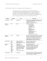
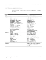
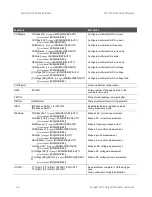
IEEE 488.2 Common Command Quick Reference

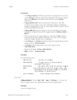
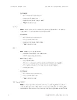
*CLS

*CLS 

 clears the Standard Event Status Register, the Operation Status Register, 

the Questionable Signal Register, and the error queue. This clears the 
corresponding summary bits (3, 5, and 7) in the Status Byte Register. 

*CLS

 does 

not affect the enable unmasks of any of the Status Registers.

Comments

Executable when Initiated: Yes

Coupled Command: No

Related Commands: 

STATus:PRESet

*RST

 Condition: none

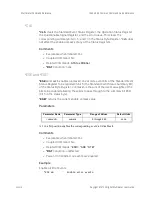
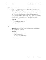
*ESE and *ESE?

*ESE <

unmask

>

  enables (unmasks) one or more event bits of the Standard Event 

Status Register to be reported in bit 5 (the Standard Event Status Summary Bit) 
of the Status Byte Register. 

<

unmask

>

 is the sum of the decimal weights of the 

bits to be enabled allowing these bits to pass through to the summary bit ESB 
(bit 5 in the status byte).

*ESE?

  returns the current enable unmask value.

Parameters

A 1 in a bit position enables the corresponding event; a 0 disables it.

Comments

Executable when Initiated: Yes

Coupled Command: No

Related Commands: 

*ESR?

*SRE

*STB?

*RST

 Condition: unaffected

Power-On Condition: no events are enabled

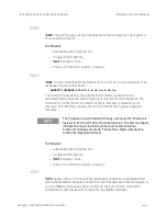
Example

Enable All Error Events

*ESE 60

Enable error events.

Parameter Name

Parameter Type

Range of Values

Default Units

<

unmask

>

numeric

0 through 255

none

Summary of Contents for E1412A

Page 1: ...Keysight E1412A 6 1 2 Digit Multimeter User Manual and SCPI Programming Guide 75000 Series C ...

Page 2: ......

Page 3: ...he terms of such license Warranty THE MATERIAL CONTAINED IN THIS DOCUMENT IS PROVIDED AS IS AND IS SUBJECT TO BEING CHANGED WITHOUT NOTICE IN FUTURE EDI TIONS FURTHER TO THE MAXIMUM EXTENT PERMITTED BY APPLICABLE LAW KEYSIGHT DISCLAIMS ALL WAR RANTIES EITHER EXPRESS OR IMPLIED WITH REGARD TO THIS MANUAL AND ANY INFORMATION CONTAINED HEREIN INCLUDING BUT NOT LIMITED TO THE IMPLIED WARRANTIES OF MER...

Page 4: ...T perform proce dures involving cover or shield removal unless you are qualified to do so DO NOT operate damaged equipment Whenever it is possible that the safety protection features built into this prod uct have been impaired either through physical damage excessive moisture or any other reason REMOVE POWER and do not use the product until safe operation can be verified by service trained personn...

Page 5: ...lly understood and met A WARNING denotes a hazard It calls attention to an operating pro cedure or practice that if not cor rectly performed or adhered to could result in personal injury or death Do not proceed beyond a WARNING notice until the indi cated conditions are fully under stood and met Products display the following sym bols Warning risk of electric shock Refer to manual for addi tional ...

Page 6: ...vi ...

Page 7: ...c volts xxxii Leakage Current Errors xxxii Rejecting Power Line Noise Voltages xxxiii Common Mode Rejection CMR xxxiv Noise Caused by Magnetic Loops xxxiv Noise Caused by Ground Loops xxxiv Resistance Measurements xxxvi 4 Wire Ohms Measurements xxxvi Removing Field Wiring Resistance Errors in 2 Wire Ohms Measurementsxxxvi Power Dissipation Effects xxxvii Settling Time Effects xxxviii Errors in Hig...

Page 8: ...Storing the dB Reference Value lii dBm Measurements lii Storing the dBm Reference Resistance Value lii LIMit Function liii Triggering the Multimeter liv The Trigger Source lvi Checking the Trigger Source lvii External Triggering lvii Internal Triggering lvii Bus Triggering lviii The Wait for Trigger State lviii The Trigger Count lix Example Setting the Trigger Count lix Checking the Trigger Count ...

Page 9: ...e File lxxix SYNCHMAV Source Code File lxxx LIMITTST Source Code File lxxxi VEE Programming Example lxxxii 3 Multimeter Command Reference Using This Chapter lxxxv Command Types lxxxv Common Command Format lxxxv SCPI Command Format lxxxv Command Separator lxxxvi Abbreviated Commands lxxxvi Implied Commands lxxxvi Parameters lxxxvii Linking Commands lxxxviii Multimeter Range and Resolution Tables lx...

Page 10: ... xcix LFRequency c LFRequency c SECure CODE c SECure STATe ci SECure STATe cii STRing cii STRing ciii VALue ciii VALue ciii ZERO AUTO civ ZERO AUTO civ CALibration cv CONFigure cvi Subsystem Syntax cvi CURRent AC cvii CURRent DC cix FREQuency cx FRESistance cx PERiod cxii RESistance cxii VOLTage AC cxiii VOLTage DC cxv VOLTage DC RATio cxvi CONFigure cxviii Subsystem Syntax cxviii DATA cxix Subsys...

Page 11: ... cxxxi RESistance cxxxi VOLTage AC cxxxiii VOLTage DC cxxxiv VOLTage DC RATio cxxxv OUTPut cxxxvii Subsystem Syntax cxxxvii TTLTrg STATe cxxxvii TTLTrg STATe cxxxviii READ cxxxix Subsystem Syntax cxxxix SAMPle cxli Subsystem Syntax cxli COUNt cxli COUNt cxlii SENSe cxliii Subsystem Syntax cxliii FUNCtion cxlv FUNCtion cxlv CURRent AC RANGe cxlvi CURRent AC RANGe cxlvi CURRent AC RANGe AUTO cxlvii ...

Page 12: ...ance APERture clix FRESistance NPLC clix FRESistance NPLC clx FRESistance RANGe clxi FRESistance RANGe clxi FRESistance RANGe AUTO clxii FRESistance RANGe AUTO clxii FRESistance RESolution clxiii FRESistance RESolution clxiii PERiod APERture clxiv PERiod APERture clxiv PERiod VOLTage RANGe clxv PERiod VOLTage RANGe clxv PERiod VOLTage RANGe AUTO clxvi PERiod VOLTage RANGe AUTO clxvi RESistance APE...

Page 13: ...DC RESolution clxxxi VOLTage DC RESolution clxxxii ZERO AUTO clxxxiii ZERO AUTO clxxxiv STATus clxxxv Subsystem Syntax clxxxv PRESet clxxxv QUEStionable CONDition clxxxv QUEStionable ENABle clxxxvi QUEStionable ENABle clxxxvi QUEStionable EVENt clxxxvi SYSTem clxxxviii Subsystem Syntax clxxxviii ERRor clxxxviii VERSion clxxxviii TRIGger cxc Subsystem Syntax cxc COUNt cxc COUNt cxci DELay cxci DELa...

Page 14: ...asuring Characteristics ccxv Operating Characteristics 5 ccxvi General Specifications ccxvii To Calculate Total Measurement Error ccxviii Understanding the of reading Error ccxviii Understanding the of range Error ccxix Total Measurement Error ccxix Error Example ccxix Interpreting Multimeter Specifications ccxx Number of Digits and Overrange ccxx Sensitivity ccxx Resolution ccxx Accuracy ccxx Tra...

Page 15: ...v 148 ccxxv 151 ccxxv 158 ccxxv 160 to 168 ccxxv 170 to 178 ccxxv 211 ccxxv 213 ccxxv 214 ccxxv 221 ccxxv 222 ccxxvi 223 ccxxvi 224 ccxxvi 230 ccxxvi 330 ccxxvi 350 ccxxvi 410 ccxxvi 420 ccxxvii 430 ccxxvii 440 ccxxvii 501 ccxxvii 502 ccxxvii 511 ccxxvii 521 ccxxvii 522 ccxxvii 531 ccxxvii 532 ccxxvii 540 ccxxvii Self Test Errors ccxxviii 602 ccxxviii 603 ccxxviii 604 ccxxviii 605 ccxxviii 606 ccx...

Page 16: ...9 ccxxix 620 ccxxix 621 ccxxix 622 ccxxix 623 ccxxix 625 ccxxix 626 ccxxix Calibration Errors ccxxx 701 ccxxx 702 ccxxx 703 ccxxx 704 ccxxx 705 ccxxx 706 ccxxx 707 ccxxx 708 ccxxx 709 ccxxx 710 ccxxxi 720 ccxxxi 721 ccxxxi 722 ccxxxi 723 ccxxxi 724 ccxxxi 725 ccxxxi 730 ccxxxi 731 ccxxxi 732 ccxxxi 733 ccxxxi 734 ccxxxi 735 ccxxxi 736 ccxxxi 740 ccxxxi 741 ccxxxi 742 ccxxxi ...

Page 17: ...on Using Special Functions and Ranges ccxxxv Resolution Example ccxxxv General Guidelines for Increasing Measurement Speed ccxxxvi Avoid Function Changes ccxxxvi Avoid Aperture Changes ccxxxvi Minimize the Number of Command Response Sessions ccxxxvi Set Autozero to ONCE or OFF ccxxxvii Turn Autorange OFF ccxxxvii Decrease Aperture Time or NPLCs ccxxxviii Setting the Resolution ccxxxviii Store the ...

Page 18: ...xviii Keysight E1412A Multimeter User Guide ...

Page 19: ...Line Frequency Reference Input Terminals and Front Panel Indicators Multimeter Functional Connections Initial Operation General Information The E1412A VXI C size Multimeter is a VXIbus message based slave device Programming the multimeter can either be through a command module using an GPIB interface or an embedded controller You use the Standard Commands for Programmable Instruments SCPI see Chap...

Page 20: ...c configuration of the address This means the address is set programmatically by the resource manager when it encounters a module with address 255 that supports dynamic configuration If you install more than one multimeter each module must have a different logical address If you use a VXIbus command module the logical address must be a multiple of eight e g 32 40 48 etc Each instrument must have a...

Page 21: ...Keysight E1412A Digital Multimeter User Guide xxi Using This Chapter Keysight E1412A Multimeter Module Setup Figure 1 1 Setting the Logical Address ...

Page 22: ...ne frequency noise in a DC voltage or ohms measurement You should set the multimeter s line frequency reference to the exact power line frequency 50 60 or 400Hz Failure to set the line frequency reference to that of your source will cause reading errors You use the CALibration LFRequency command to set the line frequency reference The default setting at power on is 60Hz If you use 50Hz or 400Hz yo...

Page 23: ...Keysight E1412A Digital Multimeter User Guide xxiii Setting the Line Frequency Reference Keysight E1412A Multimeter Module Setup Figure 1 2 Multimeter Measurement Terminals ...

Page 24: ...Connections Multimeter Functional Connections Figure 1 3 Switch Module Analog Bus Connections WARNING Shock Hazard Do not use unshrouded bare banana plugs as shown for voltages over 30 Vrms or 60 VDC For higher voltages use probe assemblies rated for the appropriate voltage and equipped with shrouded banana plugs ...

Page 25: ...1412A Digital Multimeter User Guide xxv Multimeter Functional Connections Keysight E1412A Multimeter Module Setup Figure 1 4 Frequency or Period Measurement Connections Figure 1 5 Voltage Measurement Connections ...

Page 26: ...ht E1412A Digital Multimeter User Guide Keysight E1412A Multimeter Module Setup Multimeter Functional Connections Figure 1 6 Voltage Ratio Vdc Measurement Connections Figure 1 7 2 Wire Ohms Measurement Connections ...

Page 27: ...t E1412A Digital Multimeter User Guide xxvii Multimeter Functional Connections Keysight E1412A Multimeter Module Setup Figure 1 8 4 Wire Ohms Measurement Connections Figure 1 9 Current Measurement Connections ...

Page 28: ... Instruments SCPI requires that you select the controller language e g C C Basic etc interface address and SCPI commands to be used See the 75000 Series C Installation and Getting Started Guide or equivalent for interfacing addressing and controller information The following C program verifies communication between the controller mainframe and multimeter It resets the module RST queries the identi...

Page 29: ...faultRM defaultRM viOpen defaultRM GPIB VXI0 9 24 VI_NULL VI_NULL dmm Set the timeout value to 10 seconds viSetAttribute dmm VI_ATTR_TMO_VALUE 10000 Reset the module err viPrintf dmm RST n if err VI_SUCCESS err_handler dmm err Query the module identification err viPrintf dmm IDN n if err VI_SUCCESS err_handler dmm err err viScanf dmm t buf if err VI_SUCCESS err_handler dmm err printf Module ID s n...

Page 30: ...em errors err viPrintf dmm SYST ERR n if err VI_SUCCESS err_handler dmm err err viScanf dmm t buf if err VI_SUCCESS err_handler dmm err printf System error response s n n buf end of main Error handling function void err_handler ViSession dmm ViStatus err char buf 1024 0 viStatusDesc dmm err buf printf ERROR s n buf return ...

Page 31: ...ors found in measurements and gives suggestions to help you avoid these errors DC Voltage Measurements Thermal EMF Errors Thermoelectric voltages are the most common source of error in low level dc voltage measurements Thermoelectric voltages are generated when you make circuit connections using dissimilar metals at different temperatures Each metal to metal junction forms a thermocouple which gen...

Page 32: ...for the 100Vdc and 300Vdc ranges Leakage Current Errors The multimeter s input capacitance will charge up due to input bias currents when the terminals are open circuited if the input resistance is 10G The multimeter s measuring circuitry exhibits approximately 30pA of input bias current for ambient temperatures from 0 C to 30 C Bias current will double 2 for every 8 C change in ambient temperatur...

Page 33: ...rage of the input by integrating it over a fixed period If you set the integration time to a whole number of power line cycles PLCs these errors and their harmonics will average out to approximately zero The E1412A provides three A D integration times 1 10 and 100PLCs to reject power line frequency noise and power line frequency harmonics Power line frequency defaults to 60Hz unless you specifical...

Page 34: ...r as possible Also loose or vibrating input cables will induce error voltages Make sure your input cables are tied down securely when operating near magnetic fields Whenever possible use magnetic shielding materials or physical separation to reduce problem magnetic field sources Noise Caused by Ground Loops When measuring voltages in circuits where the multimeter and the device under test are both...

Page 35: ... xxxv DC Voltage Measurements Keysight E1412A Multimeter Application Information eliminate any voltage difference between the devices Also make sure the multimeter and device under test are connected to the same electrical outlet whenever possible ...

Page 36: ...o measure small resistances Errors due to test cable resistances and contact resistances are reduced using this method Four wire ohms is often used in automated test applications where long cable lengths numerous connections or switches exist between the multimeter and the device under test The recommended connections for 4 wire ohms measurements are shown below Removing Field Wiring Resistance Er...

Page 37: ...Set to 2 wire ohms function Short the lead resistance at the DUT location CALCulate FUNCtion NULLSet math operation to NULL CALCulate STATe ON Turn math operation ON READ Measure the 2 wire ohms lead resistance Enter lead resistance value into computer The value is automatically stored in the multimeter s null offset register Remove the short from the lead resistance at the DUT location and connec...

Page 38: ...are measuring large resistances significant errors can occur due to insulation resistance and surface cleanliness You should take the necessary precautions to maintain a clean high resistance system Test cables and fixtures are susceptible to leakage due to moisture absorption in insulating materials and dirty surface films Nylon and PVC are relatively poor insulators 109 ohms when compared to PTF...

Page 39: ...dissipated in a resistance even by non sinusoidal signals The power is proportional to the square of the measured true RMS voltage independent of wave shape An average responding ac multimeter is calibrated to read the same as a true RMS meter for sine wave inputs only For other waveform shapes an average responding meter will exhibit substantial errors as shown below The multimeter s ac voltage a...

Page 40: ...he crest factor for a sine wave is 1 414 For a triangular wave the crest factor is 1 732 For a square wave with pulse width t and duty cycle T see the graphic in the previous section the crest factor is For a pulse train the crest factor is approximately equal to the square root of the inverse of the duty cycle In general the greater the crest factor the greater the energy contained in higher freq...

Page 41: ... capacitance AC Measurements Below Full Scale You can make the most accurate ac measurements when the multimeter is at full scale of the selected range Autoranging occurs at 10 and 120 of full scale This enables you to measure some inputs at full scale on one range and 10 of full scale on the next higher range e g 10V on the 10V range or 10V on the 100V range The accuracy will be significantly dif...

Page 42: ...ioning multimeter will measure the signals received The entire measurement path including the power line acts as a loop antenna Circulating currents in the loop will create error voltages across any impedances in series with the multimeter s input For this reason you should apply low level ac voltages to the multimeter through shielded cables You should connect the shield to the input LO terminal ...

Page 43: ...n Because of the capacitance between the input LO terminal and earth approximately 200 pF for the E1412A the source will experience different loading depending on how the input is applied The magnitude of the error is dependent upon the source s response to this loading The multimeter s measurement circuitry while extensively shielded responds differently in the backward input case due to slight d...

Page 44: ...s up to 50 readings per second Use manual ranging to eliminate autoranging delays By setting the preprogrammed settling trigger delays to 0 each filter will allow up to 50 readings per second However the measurement might not be very accurate since the filter is not fully settled In applications where sample to sample levels vary widely the medium filter 20Hz will settle adequately at almost 1 rea...

Page 45: ...to help you configure the multimeter for making measurements The parameters discussed in this section give you measurement flexibility when using the CONFigure command AC Signal Filter The E1412A Multimeter has three different ac filters which enable you to either optimize low frequency accuracy or achieve faster ac settling times for ac voltage or ac current measurements Only these functions use ...

Page 46: ...er can measure You can set the resolution to 4 5 or 6 digits by specifying the integration time PLCs or aperture time which is the period the multimeter s analog to digital A D converter samples the input signal for a measurement To increase measurement accuracy and improve noise rejection specify more PLCs longer integration time To increase measurement speed specify fewer PLCs shorter integratio...

Page 47: ... faster measurement use a shorter integration time Integration time applies to dc voltage dc current resistance and four wire resistance functions only The integration time for the math operations is the same as the integration time for the measurement function in use Except for FREQuency and PERiod functions integration time is usually specified in number of power line cycles NPLC The default NPL...

Page 48: ...ts the zero reading from the preceding reading This prevents offset voltages present on the multimeter s input circuitry from affecting measurement accuracy When autozero is disabled OFF the multimeter takes one zero reading and subtracts it from all subsequent measurements It takes a new zero reading each time you change function range or integration time You can disable autozero on dc voltage dc...

Page 49: ...or all inputs between 3Hz and 300kHz for the frequency and period functions The multimeter determines an internal resolution based on a 3Hz signal If you query the range the multimeter will respond with 3Hz Frequency and period measurements return 0 with no input signal applied The specified range applies to the signal connected to the Input terminals for ratio measurements Autoranging is automati...

Page 50: ...imum value following activation of the average function The minimum value is replaced with any subsequent value that is less The maximum value is replaced with any subsequent value that is greater The minimum maximum average and count are stored in volatile memory The multimeter clears the values when the average function is turned on when power is turned off or after the module is reset You use t...

Page 51: ...ore the first reading in the register After you enable the NULL function with the CALC STATe ON command the first measurement you obtain will be zero if you have not stored a value as described in the previous bullet The measured value is stored as the NULL offset value and subtracted from itself to result in the zero reading All subsequent measurements will have the offset value subtracted from t...

Page 52: ...t math function to DB CALCulate STATe ONEnable math operation CALCulate DB REFerence value Store a dB reference value dBm Measurements The dBm operation calculates the power delivered to a resistance referenced to 1 milliwatt dBm Applies to dc voltage and ac voltage measurements only You can choose from 17 different reference resistance values The factory setting for the reference resistance is 60...

Page 53: ...ter is reset or after a function change You can configure the multimeter to generate a request for service SRQ on the first occurrence of a failed reading See the Status System Register Diagram in Figure 3 1 Bits 11 and 12 of the Questionable Data Register provide the high and low limit error signals that can be enabled in the status byte to generate the request for service Use the following comma...

Page 54: ...igger configuration set by MEASure and CONFigure commands However you will need the information in this section to take advantage of the flexibility of the E1412A trigger system when using the CONFigure command The multimeter s trigger system synchronizes measurements with specified internal or external events These events include software trigger commands negative going edges on the VXIbus trigge...

Page 55: ...step process that offers triggering flexibility 1 You must configure the multimeter for the measurement by selecting the function range resolution etc 2 You must specify the source from which the multimeter will accept the trigger The multimeter will accept a BUS trigger from the VXIbus an external trigger from the front panel Trig BNC connector or an immediate trigger from the multimeter s intern...

Page 56: ...BNC connector labeled Trig on the front panel A falling negative going edge of the input signal triggers the multimeter The external pulse signal must be 1 s 5V maximum to 0V TTL levels IMMediate Internal trigger is always present If the multimeter is in the wait for trigger state INITiate TRIGger SOURce IMMediate sends the trigger The MEASure and CONFigure commands automatically set the trigger s...

Page 57: ...ive going to 0V See the following diagram for the Trig input requirement The diagram also shows the VM Complete output you can use to synchronize with a switch module The multimeter takes one reading or the number specified by SAMPle COUNt for each external trigger received on the front panel Trig BNC connector Internal Triggering The trigger signal is always present in the internal triggering mod...

Page 58: ...e IEEE 488 Group Execute Trigger GET message The multimeter must be in the wait for trigger state Send a GET from a Hewlett Packard controller with the following command TRIGGER 70903 The Wait for Trigger State You must place the multimeter in the wait for trigger state after you have configured it and selected a trigger source A trigger will not be accepted until the multimeter is in this state T...

Page 59: ...ternal triggers are received the multimeter returns to the idle state dimension array Dimension computer array CONF VOLT DC Function DC voltage TRIG SOUR EXT Trigger source is external BNC on multimeter front panel TRIG COUN 10 Multimeter will accept 10 external triggers one measurement is taken per trigger READ Place multimeter in wait for trigger state make measurements when external trigger is ...

Page 60: ... multimeter will accept 5 triggers from the external trigger BNC connector Four measurements are taken per trigger sample count is set to 4 and the trigger delay is 2 seconds dimension array Dimension computer array CONF VOLT DC Function DC voltag e TRIG SOUR EXT Trigger source is external BNC on multimeter front panel TRIG COUN 5 Multimeter will accept 5 external triggers one measurement is taken...

Page 61: ...me required before measurements to ensure measurement accuracy The default delay time is automatically updated whenever you change the function or range Once you specify a delay time value however the value does not change until you specify another value reset the multimeter or do a CONF or MEAS command Table 8 shows the default trigger delay times for all functions This delay will occur before ea...

Page 62: ... 1 1 5ms NPLC 1 1 0ms Default Trigger Delays for 2 Wire and 4 Wire Resistance Range Trigger Delay For NPLC 1 Trigger Delay For NPLC 1 100 1 5ms 1 0ms 1k 1 5ms 1 0ms 10k 1 5ms 1 0ms 100k 1 5ms 1 0ms 1M 1 5ms 10ms 10M 100ms 100ms 100M 100ms 100ms Default Trigger Delays for AC Voltage and AC Current all ranges AC Filter Trigger Delay 3Hz 300kHz filter 7 0sec 20Hz 300kHz filter 1 0sec 200Hz 300kHz fil...

Page 63: ...ets the number of readings per trigger to 1 Substituting MAX for the number parameter sets the number of readings per trigger to 50 000 Example Setting the Sample Count In the following example 10 DC voltage measurements are made when the multimeter s external trigger BNC connector is pulsed low After the 10 readings are taken the multimeter returns to the idle state dimension array Dimension comp...

Page 64: ...ter Checking the Sample Count The SAMPle COUNt MINimum MAXimum command returns one of the following numbers to the output buffer The present sample count 1 through 50 000 if neither MIN nor MAX is specified The minimum sample count available 1 if MIN is specified The maximum sample count available 50 000 if MAX is specified ...

Page 65: ...on programs written with VTL function calls can use VXIplug play drivers or SCPI commands in systems that have the VTL I O layer VTL allows you to use software from different vendors together on the same platform VTL can be used for I O application development on Microsoft Windows 3 1 and is supported on the VXI GPIB VXI and GPIB interfaces VISA 1 0 provides more VISA functionality and is fully op...

Page 66: ... GPIB software The VXI modules were loaded in a VXI C size mainframe using an E1406A or B size mainframe with E1306A Command Module as resource manager connected to the computer via the 82341 GPIB card Making Multimeter Measurements This section provides four programs that demonstrate different ways of making measurements and retrieving the readings SCPI command sequences for each program are cont...

Page 67: ...nt is greater than 1 The measurement process stops when the output buffer fills if readings are not retrieved fast enough The measurement process restarts when there is room to store readings in the output buffer INIT and FETC Commands The READ command is broken down into two operations with the INIT and FETC commands The INIT and FETC commands require that you configure the multimeter for the fun...

Page 68: ...timeter s internal memory stores 512 readings maximum MEASURE1 Source Code File Use the MEAS Command to Make a Single Measurement RST Reset the multimeter MEAS VOLT DC Configure dc volts default settings and measure retrieve the reading from the multimeter enter statement Enter reading into computer Comments The MEASure command configures the multimeter for the function specified and initiates the...

Page 69: ...er of 18 expected input is 18V the multimeter sets a range to accommodate that input which will be 100V It does not initiate the measurement Trigger source TRIG SOUR is set for an external trigger A trigger count TRIG COUN of 3 is set the multimeter will accept three external triggers The sample count SAMP COUN is set for 10 samples per trigger The INITiate command puts the multimeter in the wait ...

Page 70: ... of 18 expected input is 18V the multimeter sets a range to accommodate that input which will be 100V It does not initiate the measurement The autozero function is disabled to speed up the measurement process See the CALibrate ZERO AUTO command in the Command Reference for more information Trigger source TRIG SOUR is set for immediate internal triggers A trigger count TRIG COUN of 3 is set the mul...

Page 71: ...tion the smallest resolution value which is the best resolution It does not initiate the measurement Specifying a small value for resolution provides the most accurate measurements This will increase the integration time NPLCs and therefore require more time for the measurements Trigger source TRIG SOUR is set for an external trigger A trigger count TRIG COUN of 2 is set the multimeter will accept...

Page 72: ...ommand which transfers the readings to the output buffer You must be careful when using the INITiate and FETCh commands Internal memory stores a maximum of 512 readings the oldest readings exceeding 512 are lost Synchronizing the Multimeter With a Switch Module This program example demonstrates how to synchronize the multimeter with a switch module For the E1412A it uses the TTL triggers from the ...

Page 73: ...n Figure 2 4 This example program enables the switch s Scan Complete bit to allow it to set the OPR bit in the switch s status byte when the scan is finished The program repeatedly reads the switch module s status byte until the OPR bit gets set which returns a status byte value of 128 This indicates the switch module has completed all closures in the scan list The multimeter s FETC command causes...

Page 74: ...e Keysight E1412A Multimeter Application Information E1412A Multimeter Application Examples Figure 2 4 E1476A Switch Module Status System NOTE This is the E1476A Switch Module s status system See Figure 2 5 for the E1412A Multimeter status system GPIB ...

Page 75: ...rigger multimeter TRIG COUN 8 Multimeter will accept 8 triggers TRIG DEL 0 01 Use a 10 ms delay before each measurement OUTP TTLT1 STAT ON Output VM Complete to switch via TTLT1 CALC FUNC AVER Select the math function AVERage CALC STAT ON Enable math operations OPC Wait until above commands are processed Read the response to the OPC command from multimeter INIT Puts multimeter in the wait for trig...

Page 76: ...surement multimeter sends TTLT1 VM Complete back to switch module to advance scan to the next channel measurements are stored in multimeter internal memory Read switch s status byte until all channels are scanned and scan complete bit 8 in the operation status register sets the OPR bit in the status byte Retrieve the readings from the multimeter FETC Transfer measurements from the multimeter inter...

Page 77: ...dings when they are available Figure 2 5 illustrates the E1412A status system A Questionable Data Register an Output Buffer and a Standard Event Register each have a respective status bit in the Status Byte Register The Output Buffer sets the MAV bit when there is data available such as measurement readings or a response to a SCPI query command The Questionable Data Register and Standard Event Reg...

Page 78: ...lxxviii Keysight E1412A Digital Multimeter User Guide Keysight E1412A Multimeter Application Information E1412A Multimeter Application Examples Figure 2 5 E1412A Multimeter Status System GPI ...

Page 79: ...er RST Reset the multimeter CLS Clear the multimeter s status registers ESE 1 Enables bit 0 of the multimeter s standard event register CONF VOLT 15 Configure for dc volts expected input of 15V VOLT DC NPLC 10 Set number of power line cycles to 10 TRIG COUN 10 Multimeter will accept 10 triggers TRIG DEL 01 Use a 10ms delay before each measurement CALC FUNC AVER Select the math function AVERage CAL...

Page 80: ...AV Source Code File This program has the multimeter take 10 measurements just like SYNCHOPC Readings are transferred to the output buffer by a FETC command The Message Available bit MAV in the status byte see Figure 2 5 is monitored to detect when the measurements are complete and the Multimeter has readings in the output buffer Readings are retrieved by the computer when the MAV bit in the status...

Page 81: ...ut before measurements complete FETC expects a response before the timeout interval specified in the program code Using the previous program detecting the OPC bit is recommended Retrieve the AVERage math operation response from the multimeter CALC AVER AVER Retrieve the average measurement value CALC AVER MAX Retrieve the maximum measurement value CALC AVER MIN Retrieve the minimum measurement val...

Page 82: ...TAT QUES ENAB 6144 Unmask the limit error bits Loop READ Trigger measurement and place response into the output buffer Enter response into the computer SPOLL read the multimeter s status byte until bit 3 QUE goes high to indicate there is a Limit Test Failure HI or LO Wait 1 second End Loop Check the multimeter for system errors SYST ERR Retrieve the system error response from the multimeter VEE P...

Page 83: ...lect the Direct I O button from the Instrument Type choices Then select Add Instrument from the Instrument Configure choices This selection pops up the Device Configuration dialog box 3 Fill in the Device Configuration Name Interface Address and Timeout Set Byte Ordering to MSB and Live Mode to ON Then select Direct I O Config The Direct I O Configuration dialog box pops up 4 Verify Conformance is...

Page 84: ... a Strip Chart Display object that displays the readings of the eight channels The Strip Chart has an Auto Scale button to automatically scale the horizontal and vertical axis to best display the measured data Upper and lower boundary traces could be added to the strip chart s display See your VEE documentation and on line help for more detail on test and measurement I O control If you are not usi...

Page 85: ...er and may include one or more parameters The command keyword is separated from the first parameter by a space character Some examples of common commands are shown below RST ESR 32 STB SCPI Command Format The SCPI commands perform functions such as making measurements querying instrument states or retrieving data The SCPI commands are grouped into command subsystem structures A command subsystem s...

Page 86: ...orm For better program readability you may send the entire command The instrument will accept either the abbreviated form or the entire command For example if the command syntax shows MEASure then MEAS and MEASURE are both acceptable forms Other forms of MEASure such as MEASU or MEASUR will generate an error Additionally SCPI commands are case insensitive Therefore you may use upper or lower case ...

Page 87: ...AX command If you send the command without specifying a MINimum or MAXimum parameter the present TRIGger COUNt value is returned If you send the MIN parameter the command returns the minimum trigger count allowable If you send the MAX parameter the command returns the maximum trigger count allowable Be sure to place a space between the command and the parameter Table 4 1 Parameter Types Parameter ...

Page 88: ... only a semicolon between commands within the same subsystem For example to set trigger count trigger delay and the trigger source which are all set using the TRIGger subsystem send the following SCPI string TRIG COUNt 10 DELay 05 SOURce TTLT4 Linking Multiple SCPI Commands of Different Subsystems Use both a semicolon and a colon between commands of different subsystems For example a SAMPle and OU...

Page 89: ...30 V 100 V 1mV 100V 120V 30 V 100 V 300 V 1mV 10mV 300V 300V 300 V 1mV 3mV 10mV 100mV Table 4 3 DC Current Resolution versus Integration Time or Aperture Time Integration Time in Power Line Cycles PLCs Aperture Time for 60Hz Line Frequency seconds Range Maximum Reading 100 PLCs 1 67s 10 PLCs 167ms 1 PLC 16 7ms 0 2 PLC 3 33ms 0 02 PLC 0 333ms 10mA 12mA 3nA 10nA 30nA 100nA 1 A 100mA 120mA 30nA 100nA...

Page 90: ...ge versus Resolution Resolution Choices versus Range RANGE 100mV 1V 10V 100V 300V MIN 100nV 1 V 10 V 100 V 1mV power on and RST setting 1 V 10 V 100 V 1mV 10mV MAX 10 V 100 V 1mV 10mV 100 mV Table 4 6 AC Current Range versus Resolution Resolution Choices versus Range RANGE 1A 3A MIN 1 A 3 A power on and RST setting 10 A 30 A MAX 100 A 300 A ...

Page 91: ... Measurement CONF VOLT DC Function DC voltage TRIG SOUR BUS Trigger source is BUS trigger INIT Place multimeter in wait for trigger state ABOR Abort waiting for a trigger and place multimeter in idle state Comments ABORt does not affect any other settings of the trigger system When the INITiate command is sent the trigger system will respond as it did before ABORt was executed ABORt returns the mu...

Page 92: ... combination If you choose a math operation that is not allowed with the present measurement function math is turned off If you select a valid math operation and then change to one that is invalid a Settings conflict error is generated over the remote interface For null and dB measurements you must turn on the math operation before writing to their math registers Subsystem Syntax CALCulate AVERage...

Page 93: ...the number of readings taken since AVERage was enabled CALC FUNC AVER and CALC STAT ON commands The count value is cleared when AVERage is enabled by the CALC FUNC AVER and CALC STAT ON commands when power has been off or after a remote interface reset The number of readings taken is stored in volatile memory Example Query the Number of Readings Since the AVERage Math Operation was Enabled CALC CO...

Page 94: ...ce value MIN MAX stores a relative value in the dB Relative Register You must turn on the math operation e g execute CALC STAT ON before writing to the math register You can set the relative value to any number between 200dBm the MIN and MAX values The dB reference is stored in volatile memory Example Set the DB Reference Value CALC STAT ON Turn on the math operation CALC DB REF 60 Sets DB referen...

Page 95: ... Example Query the DBM Reference Value Set for the DBM Math Operation CALC DBM REF Query the DBM reference value FUNCtion CALCulate FUNCtion AVERage DB DBM LIMit NULL selects the math function to be used One function is enabled at a time with NULL the default The selected function MUST be enabled with CALC STATe ON Parameter Summary AVERage measurements store the minimum and maximum readings from ...

Page 96: ...CALCulate FUNCtion queries the multimeter to determine the present math function Returns AVER DB DBM LIM or NULL Example Query the Calculate Math Function CALC FUNC Query the calculate function LIMit LOWer CALCulate LIMit LOWer value MIN MAX sets the lower limit for limit testing You can set the value to any number between 0 and 120 of the highest range for the present function MIN 120 of the high...

Page 97: ...TAT ON Turn on the math operation CALC LIM UPP 3000 Set the upper limit CALC FUNC LIM Select the LIMit math operation You can select the calculate function at any time before or after enabling the calculate state LIMit UPPer CALCulate LIMit UPPer MIN MAX queries the upper limit Example Query the Upper Limit Set for the LIMit Math Operation CALC LIM UPP Queries the upper limit NULL OFFSet CALCulate...

Page 98: ...MIN MAX queries the null value Example Query the Null Offset Value Set for the NULL Math Operation CALC NULL OFFS Query the null offset value STATe CALCulate STATe OFF ON disables or enables the selected math function The state is stored in volatile memory Example Enable the Currently Selected Calculate Math Function CALC STAT ON The selected or default math function is enabled STATe CALCulate STA...

Page 99: ...on COUNt LFRequency 50 60 400 LFRequency MIN MAX SECure CODE new code SECure STATe OFF ON code SECure STATe STRing quoted string STRing VALue cal_value VALue ZERO AUTO ON OFF ZERO AUTO COUNt CALibration COUNt queries the multimeter to determine the number of times a point calibration has occurred A complete calibration of the multimeter increases the count by the number of points calibrated It is ...

Page 100: ... CALibration LFRequency queries the line frequency setting Comments This command returns 50 for line frequency set to 400 because 400 is an even multiple of 50 Example Query the Line Frequency Setting CAL LFR Query the line frequency SECure CODE CALibration SECure CODE new code enters a new calibration security code To change the security code first unsecure the multimeter using the old security c...

Page 101: ...T OFF HP_E1412 Unsecure with the old code CAL SEC CODE the_new_code Enter a new calibration code a maximum of 12 characters SECure STATe CALibration SECure STATe OFF ON code unsecures or secures the multimeter for calibration The calibration code must be the code set by the CAL SEC CODE command The state is stored in non volatile memory Parameters Comments You can substitute decimal values for the...

Page 102: ...on date and or the next calibration due date The calibration message can contain up to 40 characters Characters in excess of 40 are truncated and no error is generated The string is stored in non volatile memory Parameters Comments The calibration message can contain up to 40 characters Calibration security state must be OFF to store a string The calibration message is stored in non volatile memor...

Page 103: ...nal used by the calibration procedure See the E1412A Service Manual Chapter 5 Adjustments for a more detailed description of the multimeter s calibration adjustment procedures Parameters Comment RST does not affect the calibration value Example Enter the Known Value for the Calibration Source Signal CAL VAL 10 0 Enter calibration value VALue CALibration VALue queries the present calibration value ...

Page 104: ...easurement accuracy The OFF parameter disables autozero In this mode the multimeter takes one zero measurement and subtracts it from all subsequent input signal measurements prior to a change in function range or integration time A new zero measurement is made following a change in function range or integration time This mode increases measurement speed because a zero measurement is not made for e...

Page 105: ... input terminals The command returns 0 to indicate there are no calibration errors and the calibration was performed A 1 is returned if a calibration error occurs and a calibration is unable to be performed The error message is reported to the output buffer You must set CALibration SECure STATe OFF code to allow a calibration to be performed This requires that you know the calibration secure code ...

Page 106: ...ent DC range MIN MAX DEF AUTO resolution MIN MAX DEF FREQuency range MIN MAX DEF AUTO resolution MIN MAX DEF FRESistance range MIN MAX DEF AUTO resolution MIN MAX DEF PERiod range MIN MAX DEF AUTO resolution MIN MAX DEF RESistance range MIN MAX DEF AUTO resolution MIN MAX DEF Command Setting RANGe As specified or AUTO RESolution As specified or as a function of range integration time or NPLCs AC f...

Page 107: ...sts the default settings you can expect from the CONFigure command for each function CURRent AC CONFigure CURRent AC range MIN MAX DEF AUTO resolution MIN MAX DEF selects the AC current function and allows you to specify the measurement range and resolution See the range versus resolution table at the beginning of this chapter for valid resolution choices for each ac current range Parameters Table...

Page 108: ...r do not specify a value for the range and resolution parameters see next bullet comment In the autorange mode the multimeter samples the input signal before each measurement and selects the appropriate range To specify the MIN or MAX resolution while autoranging you must specify the AUTO or DEF parameter for range and specify MIN or MAX e g CONF CURR AC DEF MIN or CONF CURR AC DEF MAX or CONF CUR...

Page 109: ...ters select the minimum or maximum values for range and resolution For range MIN 10 mA MAX 3A For resolution See Table 3 1 for valid resolution choices for each range To select autorange specify AUTO or DEF for range or do not specify a value for the range and resolution parameters see next bullet comment In the autorange mode the multimeter samples the input signal before each measurement and sel...

Page 110: ...n Parameters Comments The frequency function uses one range for all inputs between 3Hz and 300kHz A frequency measurement returns 0 if no input is applied Range and resolution settings are listed below for the MIN MAX DEF and AUTO parameters and the settings after a module reset RST FRESistance CONFigure FRESistance range MIN MAX DEF AUTO resolution MIN MAX DEF selects the 4 wire ohms function and...

Page 111: ...ify a value for the range and resolution parameters In the autorange mode the multimeter samples the input signal before each measurement and selects the appropriate range To specify a MIN or MAX resolution while autoranging you must specify the AUTO or DEFault parameter CONF FRES DEF MIN or CONF FRES DEF MAX or CONF FRES AUTO MIN or CONF FRES AUTO MAX you cannot omit the range parameter This prev...

Page 112: ...below for the MIN MAX DEF and AUTO parameters and the settings after a module reset RST RESistance CONFigure RESistance range MIN MAX DEF AUTO resolution MIN MAX DEF selects the 2 wire ohms function and allows you to specify the range and resolution Parameters Parameter Name Parameter Type Range of Values Default Units range numeric 3 33E 01 Sec resolution numeric 3 33E 05 3 33E 06 3 33E 07 Sec PA...

Page 113: ...solution parameters In the autorange mode the multimeter samples the input signal before each measurement and selects the appropriate range To specify a MIN or MAX resolution while autoranging you must specify AUTO or DEFault for range CONF RES DEF MIN or CONF RES DEF MAX or CONF RES AUTO MIN or CONF RES AUTO MAX you cannot omit the range parameter This prevents the MIN or MAX resolution from bein...

Page 114: ...In the autorange mode the multimeter samples the input signal before each measurement and selects the appropriate range To specify a MIN or MAX resolution while autoranging you must specify AUTO or DEFault for range CONF VOLT AC DEF MIN or CONF VOLT AC DEF MAX or CONF VOLT AC AUTO MIN or CONF VOLT AC AUTO MAX you cannot omit the range parameter This prevents the MIN or MAX resolution from being in...

Page 115: ...rst resolution the largest value for the selected range See Table 3 1 for valid resolution choices for each range To select autorange specify DEFault for range or do not specify a value for the range and resolution parameters In the autorange mode the multimeter samples the input signal before each measurement and selects the appropriate range To specify a MIN or MAX resolution while autoranging y...

Page 116: ...s The specified range in the command applies to the signal connected to the HI and LO input terminals Parameters Comments To select a standard measurement range specify range as the input signal s maximum expected voltage The multimeter then selects the correct range to accept the input The AUTO or DEFault option for the range parameter enables autorange The DEFault option for resolution defaults ...

Page 117: ...ltimeter User Guide cxvii CONFigure Multimeter Command Reference For resolution MIN selects the best resolution the smallest value for the selected range MAX selects the worst resolution the largest value for the selected range ...

Page 118: ...le CURR AC 1 000000E 00 1 000000E 05 CURR 1 000000E 00 1 000000E 05 VOLT AC 2 000000E 02 1 000000E 06 VOLT 3 000000E 02 1 000000E 06 FRES 100 0000E 03 1 000000E 05 RES 1 000000E 03 1 000000E 03 FREQ 3 000000 00 3 000000E 05 PER 3 333330E 01 3 333330E 06 If you specify DEF MIN or MAX for the range or resolution parameters in CONFigure or MEASure the CONFigure command returns the selected value Rela...

Page 119: ...nd uses internal memory to store readings prior to a FETCh command e g when a measurement is initiated by the INITiate command You can query the number of stored readings in memory by sending the DATA POINts command Comments INITiate command uses internal memory to store readings prior to using a FETCh command You use the DATA POINts command to query the number of readings stored in internal memor...

Page 120: ...utput buffer can consist of two different lengths bytes or characters in Real ASCII format 1 23456E 12 LF or 1 234567E 12 LF Each measurement is terminated with a Line Feed LF The GPIB End or Identify EOI signal is sent with the last byte transferred If multiple measurements are returned the measurements are separated by commas and EOI is sent only with the last byte For example 1 23456E 12 LF 1 2...

Page 121: ...ultimeter Command Reference CONF VOLT DC Function DC voltage SAMP COUN 100 100 readings per trigger INIT Store readings in internal memory trigger source is IMMediate by default FETC Place readings in output buffer enter statement Enter readings into computer ...

Page 122: ...red in internal memory as soon as INITiate is executed Readings stored in memory from previous commands are replaced by the new readings To transfer readings from memory to the output buffer use the FETCh command If TRIGger SOURce is not IMMediate the measurement starts as soon as a trigger is received either from the external BNC connector the VXIbus backplane TTLT n trigger lines or a BUS trigge...

Page 123: ...Keysight E1412A Digital Multimeter User Guide cxxiii INITiate Multimeter Command Reference INIT You must re initiate the wait for trigger state after each trigger cycle ...

Page 124: ...intains its input impedance of 10M for all DC voltage ranges This is useful to prevent a change in input impedance caused by changing ranges from affecting the measurements Parameters Example Enable Automatic Input Impedance use 10G for 100mV 1V and 10V ranges INP IMP AUTO ON Enable automatic input impedance Comments You can substitute decimal values for the OFF 0 and ON 1 parameters RST Condition...

Page 125: ...ns a number to show whether the automatic input impedance mode is enabled or disabled 1 ON 0 OFF The number is sent to the output buffer Example Query the Input Impedance Mode INP IMP AUTO ON Enable automatic input impedance INP IMP AUTO Query multimeter to return input impedance mode 1 enter statement Enter value into computer ...

Page 126: ...ERiod range MIN MAX DEF AUTO resolution MIN MAX DEF RESistance range MIN MAX DEF AUTO resolution MIN MAX DEF VOLTage AC range MIN MAX DEF AUTO resolution MIN MAX DEF VOLTage DC range MIN MAX DEF AUTO resolution MIN MAX DEF VOLTage DC RATio range MIN MAX DEF AUTO resolution MIN MAX D EF Command Setting RANGe As specified or AUTO RESolution As specified or as a function of range integration time or ...

Page 127: ... Table 3 5 for resolution choices To select autorange specify DEF for range or do not specify a value for the parameter In the autorange mode the multimeter samples the input signal before each measurement and selects the appropriate range To specify a MIN or MAX resolution while autoranging you must specify the AUTO or DEFault parameter for the range parameter as MEAS CURR AC DEF you cannot omit ...

Page 128: ...mum or maximum values for range and resolution For range MIN 10mA MAX 3A For resolution MIN selects the best resolution the smallest value for the selected range MAX selects the worst resolution the largest value for the selected range To select autorange specify DEF for range or do not specify a value for the range and resolution parameters In the autorange mode the multimeter samples the input s...

Page 129: ...e range for all inputs between 3Hz and 300kHz Querying the range will always return 3E 00 A frequency measurement returns 0 if no input is applied Range and resolution settings are listed below for the MIN MAX DEF and AUTO parameters and after a module reset RST FRESistance MEASure FRESistance range MIN MAX DEF AUTO resolution MIN MAX DEF selects the 4 wire ohms function and allows you to specify ...

Page 130: ...the largest value for the selected range To select autorange specify AUTO or DEF for range or do not specify a value for the range and resolution parameters In the autorange mode the multimeter samples the input signal before each measurement and selects the appropriate range To specify a MIN or MAX resolution while autoranging you must specify MEAS FRES DEF you cannot omit the range parameter Thi...

Page 131: ...N MAX DEF and AUTO parameters and after a module reset RST RESistance MEASure RESistance range MIN MAX DEF AUTO resolution MIN MAX DEF selects the 2 wire ohms function and allows you to specify the range and resolution Parameters Parameter Name Parameter Type Range of Values Default Units range numeric 3 33E 01 Sec resolution numeric 3 33E 05 3 33E 06 3 33E 07 Sec PARAMETER RANGE RESOLUTION MIN 3 ...

Page 132: ...value for the selected range MAX selects the worst resolution the largest value for the selected range To select autorange specify DEF for range or do not specify a value for the range and resolution parameters In the autorange mode the multimeter samples the input signal before each measurement and selects the appropriate range To specify a MIN or MAX resolution while autoranging you must specify...

Page 133: ...e best resolution the smallest value for the selected range MAX selects the worst resolution the largest value for the selected range See Table 3 4 for valid resolution choices for each range To select autorange specify DEF for range or do not specify a value for the range and resolution parameters In the autorange mode the multimeter samples the input signal before each measurement and selects th...

Page 134: ...resolution the smallest value for the selected range MAX selects the worst resolution the largest value for the selected range See Table 3 1 for valid resolution choices for each range To select autorange specify DEFault for range or do not specify a value for the range and resolution parameters In the autorange mode the multimeter samples the input signal before each measurement and selects the a...

Page 135: ...d voltage The multimeter then selects the correct range to accept the input The AUTO or DEFault option for the range parameter enables autorange The DEF option for the resolution parameter defaults the integration time to 10 PLC The MIN and MAX parameters select the minimum or maximum values for range and resolution For range MIN 100mV MAX 300V For resolution MIN selects the best resolution the sm...

Page 136: ... DEF you cannot omit the range parameter This prevents the MIN or MAX resolution from being interpreted as a range setting and the resulting command becomes MEAS VOLT DC RAT DEF MIN or MEAS VOLT DC RAT DEF MAX Related Commands FETCh INITiate READ Example Making DC Voltage Ratio Measurements MEAS VOLT DC RAT 0 825 MAX Function DC voltage range selected 1V MAX resolution 100 V ...

Page 137: ... voltmeter complete signal is always routed to the multimeter s front panel VM Complete BNC connector When enabled ON the OUTPut command also routes voltmeter complete to the specified trigger line on connector P2 When disabled OFF voltmeter complete is routed only to the multimeter s front panel connector The multimeter generates the voltmeter complete signal after it has sampled the input for ea...

Page 138: ...ON Route signal to trigger line 7 TTLTrg STATe OUTPut TTLTrg n STATe returns a number to show whether VXIbus trigger line routing of the voltmeter complete signal is enabled or disabled 1 ON 0 OFF The number is sent to the output buffer Example Query Voltmeter Complete Destination OUTP TTLT7 ON Route signal to trigger line 7 OUTP TTLT7 Query multimeter to return trigger line mode enter statement E...

Page 139: ...ntify EOI signal is sent with the last byte transferred If multiple readings are returned the readings are separated by commas and EOI is sent only with the last byte The output buffer capacity is 128 bytes The multimeter remains busy with a full buffer until you begin removing readings from it Readings are placed directly in the output buffer and are not stored in internal memory as with an INIT ...

Page 140: ...rence READ CONF VOLT DC Function DC voltage SAMP COUN 100 Specify 100 readings per trigger READ Place multimeter in wait for trigger state and make measurements send readings to output buffer trigger source is IMMediate by default enter statement Enter readings into computer ...

Page 141: ...0 is specified for number the command executes without error When an INIT is executed requiring readings to be stored in internal memory an Insufficient memory error is generated to show that the number of readings exceeds the memory available However you can execute READ which returns the readings to the output buffer and does not use internal memory A number 50 000 returns Error 222 Data out of ...

Page 142: ... readings into computer COUNt SAMPle COUNt MIN MAX returns one of the following numbers to the output buffer The present sample count 1 through 50 000 if MINimum or MAXimum is not specified The minimum sample count 1 if MIN is specified The maximum sample count 50 000 if MAX is specified Example Query the Sample Count SAMP COUN 10 Specify 10 readings per trigger SAMP COUN Query multimeter to retur...

Page 143: ...NCtion CURRent DC FUNCtion FREQuency FUNCtion FRESistance FUNCtion PERiod FUNCtion RESistance FUNCtion VOLTage AC FUNCtion VOLTage DC FUNCtion VOLTage DC RATio FUNCtion CURRent AC RANGe range MIN MAX AC RANGe MIN MAX AC RANGe AUTO OFF ON AC RANGe AUTO AC RESolution resolution MIN MAX AC RESolution MIN MAX DC APERture 333ms 3 33ms 16 7ms 167ms 1 67s MIN MAX DC APERture MIN MAX DC NPLCycles 02 2 1 1...

Page 144: ...e MIN MAX VOLTage RANGe AUTO OFF ON VOLTage RANGe AUTO RESistance APERture 333ms 3 33ms 16 7ms 167ms 1 67s MIN MAX APERture MIN MAX NPLCycles 0 02 0 2 1 10 100 MIN MAX NPLCycles MIN MAX RANGe range MIN MAX RANGe MIN MAX RANGe AUTO OFF ON RANGe AUTO RESolution resolution MIN MAX RESolution MIN MAX VOLTage AC RANGe range MIN MAX AC RANGe MIN MAX AC RANGe AUTO OFF ON AC RANGe AUTO AC RESolution resol...

Page 145: ...on CONF VOLT Function DC voltage FUNC FRES Set function to 4 wire resistance READ Place multimeter in wait for trigger state and make measurement send reading to output buffer enter statement Enter reading into computer FUNCtion SENSe FUNCtion returns one of the following quoted strings to the output buffer CURR AC CURR FREQ FRES PER Parameter Name Parameter Type Range of Values Default Units func...

Page 146: ...pected current The multimeter then selects the correct range MIN selects the minimum range available with the CURRent AC RANGe command 1A MAX selects the maximum range available 3A You must select a range using CURRent AC RANGe before specifying resolution Specifying a fixed range disables the autorange mode set by the CURR AC RANG AUTO command The CURR AC RANG command overrides the range setting ...

Page 147: ...e present range enter statement Enter value into computer CURRent AC RANGe AUTO SENSe CURRent AC RANGe AUTO mode enables or disables the autorange function for AC current measurements Parameters Comments You can substitute decimal values for the OFF 0 and ON 1 parameters When autoranging is ON the multimeter samples the input before each measurement and selects the appropriate range If you explici...

Page 148: ...mallest value for the selected range MAXimum selects the worst resolution the largest value for the selected range You must select a range using CURRent AC RANGe before specifying resolution Also only specify a resolution when making measurements on a fixed range Otherwise the resolution will change to correspond with the range selected during autoranging Specify resolution in the same units as th...

Page 149: ...seconds 50Hz Setting the aperture time also sets the integration time in power line cycles PLCs and the resolution For example an aperture time of 16 7ms 60Hz line frequency sets an integration time of 1 PLC The corresponding resolution depends on the function and range you select The CURR DC APER command overrides the results of previously executed CURR DC NPLC and CURR DC RES commands The last c...

Page 150: ... number of PLCs shown in the following table Parameters Comments MINimum selects 0 02 PLCs MAXimum selects 100 PLCs Setting the integration time in power line cycles PLCs also sets the aperture time and the resolution For example 10 PLCs sets an aperture time of 167ms 60Hz line frequency or 200ms 50Hz The corresponding resolution depends on the function and range you select The CURR DC NPLC comman...

Page 151: ... DC Current Integration Time CURR DC NPLC 100 Integration time is 100 PLCs CURR DC NPLC Query multimeter to return integration time enter statement Enter value into computer CURRent DC RANGe SENSe CURRent DC RANGe range selects the range for DC current measurements Parameters Comments To select a standard measurement range specify range as the input signal s maximum expected current The multimeter...

Page 152: ...t specified Only the ranges available with the RANGe command are returned For example if CONFigure selects the 100mA range 100mA is the range returned The minimum current range available 10mA if MIN is specified The maximum current range available 3A if MAX is specified Example Query the DC Current Measurement Range CURR DC RANG 3 Select 3A range CURR DC RANG Query multimeter to return the present...

Page 153: ...s a number to show whether the DC current autorange mode is enabled or disabled 1 ON 0 OFF The number is sent to the output buffer Example Query the DC Current Autorange Mode CURR DC RANG AUTO OFF Disable autorange CURR DC RANG AUTO Query multimeter to return autorange mode enter statement Enter value into computer CURRent DC RESolution SENSe CURRent DC RESolution resolution selects the resolution...

Page 154: ...MAX is not specified Only the resolutions available with the RESolution command are returned For example if CONFigure selects 10mA resolution 10mA is the resolution returned The minimum current resolution available 1 A if MIN is specified The maximum current resolution available 100 A if MAX is specified Example Query the DC Current Measurement Range CURR DC RES 3Select 3A resolution CURR DC RES Q...

Page 155: ...measurements The ac filter selection is stored in volatile memory and returns to the 20Hz filter medium when power is removed or after a module reset The upper limit on all three filters is 300kHz The slow filter is 3Hz the medium filter is 20Hz and the fast filter is 200Hz The CONFigure and MEASure commands select the 20Hz filter RST Condition DET BAND 20 medium filter Example Set the ac Signal F...

Page 156: ...N 0 01 MAX 1 RST Condition 0 1 seconds Example Set a Frequency Aperture Time of 1 Second FREQ APER 1 Sets aperture time to 1 second FREQuency APERture SENSe FREQuency APERture MIN MAX queries the aperture time for frequency measurements The MIN parameter returns the minimum aperture value 0 01 the MAX parameter returns the maximum aperture value 1 FREQuency VOLTage RANGe SENSe FREQuency VOLTage RA...

Page 157: ...ltage Range for Frequency Measurements to 100V FREQ VOLT RANG 100 Voltage range for frequency measurements is 100V FREQuency VOLTage RANGe SENSe FREQuency VOLTage RANGe MIN MAX returns one of the following numbers to the output buffer 0 1 1 10 100 or 300 The present voltage range selected if MIN or MAX is not specified The minimum voltage range available 100mV if MIN is specified The maximum volta...

Page 158: ... RANG AUTO OFF Disable autorange FREQuency VOLTage RANGe AUTO SENSe FREQuency VOLTage RANGe AUTO returns a number to show whether the autorange mode is enabled or disabled 1 ON 0 OFF The number is sent to the output buffer Example Query the Autorange Mode FREQ VOLT RANG AUTO OFF Disable autorange FREQ VOLT RANG AUTO Query multimeter to return autorange mode enter statement Enter value into compute...

Page 159: ...ority The greater the aperture time the greater the normal mode rejection and the lower the reading rate Related Commands CALibration LFRrequency RST Condition FRES APER 0 166667 seconds 60Hz or FRES APER 0 20000 50Hz Example Set an Aperture Time of 16 7ms FRES APER 16 7E 03 Aperture time is 16 7ms FRESistance APERture SENSe FRESistance APERture MIN MAX returns one of the following numbers to the ...

Page 160: ...ine frequency or 200ms 50Hz The corresponding resolution depends on the function and range you select The FRES NPLC command overrides the results of previously executed FRESistance APERture and FRESistance RESolution commands the last command executed has priority The greater the number of PLCs the greater the normal mode rejection and the lower the reading rate Only the 1 PLC 10 PLC and 100 PLC s...

Page 161: ...ct a standard measurement range specify range as the input signal s maximum expected resistance The multimeter then selects the correct range MIN selects the minimum range available with the FRESistance RANGe command 100 MAX selects the maximum range available 100 You must select a range using FRESistance RANGe before specifying resolution Specifying a fixed range disables the autorange mode set b...

Page 162: ...ent Range FRES RANG 100 Select 100 range FRES RANG Query multimeter to return the present range enter statement Enter value into computer FRESistance RANGe AUTO SENSe FRESistance RANGe AUTO mode enables or disables the autorange function for 4 wire resistance measurements Parameters Comments You can substitute decimal values for the OFF 0 and ON 1 parameters When autoranging is ON the multimeter s...

Page 163: ... 4 wire resistance measurements Parameters Comments MINimum selects the best resolution the smallest value for the selected range MAXimum selects the worst resolution the largest value for the selected range You must select a range using FRESistance RANGe before specifying resolution Also only specify a resolution when making measurements on a fixed range Otherwise the resolution will change to co...

Page 164: ...3E 03 Set resolution to 0 3m FRES RES Query multimeter to return the present resolution enter statement Enter value into computer PERiod APERture SENSe PERiod APERture time MIN MAX sets the integration time in seconds Values for time are rounded up to the nearest aperture time shown in the following table Parameters Comments MINimum sets the aperture time to 10ms MAXimum sets the aperture time to ...

Page 165: ...ry multimeter to return aperture time enter statement Enter value into computer PERiod VOLTage RANGe SENSe PERiod VOLTage RANGe range selects the voltage range for the signal level of period measurements Parameters Comments To select a standard measurement range specify range as the input signal s maximum expected voltage The multimeter then selects the correct range MIN selects the minimum range ...

Page 166: ...eriod measurements enter statement Enter response into computer PERiod VOLTage RANGe AUTO SENSe PERiod VOLTage RANGe AUTO mode enables or disables the autorange function for the signal level of period measurements Parameters Comments You can substitute decimal values for the OFF 0 and ON 1 parameters When autoranging is ON the multimeter samples the input before each measurement and selects the ap...

Page 167: ...lues are rounded up to the nearest aperture time shown in the following table Parameters Comments MIN sets the aperture time to 0 333ms MAX sets the aperture time to 1 66667 seconds 60Hz or 2 seconds 50Hz Setting the aperture time also sets the integration time in power line cycles PLCs and the resolution For example an aperture time of 16 7ms 60Hz line frequency sets an integration time of 1 PLC ...

Page 168: ...The minimum aperture time available 333 ms if MIN is specified The maximum aperture time available 1 67s 60Hz 2s 50Hz if MAX is specified Example Query the Aperture Time RES APER 167E 03 Aperture time is 167ms RES APER Query multimeter to return aperture time enter statement Enter value into computer RESistance NPLC SENSe RESistance NPLCycles number sets the integration time in power line cycles P...

Page 169: ...jection and the lower the reading rate Only the 1 PLC 10 PLC and 100 PLC settings provide normal mode rejection of 50Hz or 60Hz power line related noise RST Condition 10 PLC Example Set the Integration Time in PLCs RES NPLC 100 Integration time is 100 PLCs RESistance NPLC SENSe RESistance NPLC MIN MAX returns one of the following numbers to the output buffer The present integration time in PLCs if...

Page 170: ...igure command on the same function The multimeter uses the same aperture time to set the resolution on the new range as was selected by CONFigure RST Condition RES RANG 1k Example Change the Range CONF RES 1320 MAX Function 2 wire ohms range selected 10k MAX resolution 1 RES RANG 220 Range selected 1k MAX resolution 0 1 READ Place multimeter in wait for trigger state and make measurements send rea...

Page 171: ...rements Parameters Comments You can substitute decimal values for the OFF 0 and ON 1 parameters When autoranging is ON the multimeter samples the input before each measurement and selects the appropriate range If you explicitly select a range using RESistance RANGe autoranging is turned OFF Related Commands CONFigure RESistance RANGe RST Condition RES RANG AUTO ON Example Disable Autoranging RES R...

Page 172: ...specify a resolution when making measurements on a fixed range Otherwise the resolution will change to correspond with the range selected during autoranging If autoranging is required set the resolution using the MIN or MAX parameters If necessary to achieve the specified resolution the multimeter will increase the integration time as needed This command overrides the results of previously execute...

Page 173: ...NGe command are returned The resolution with the smallest value i e the best resolution for the selected range if MIN is specified The resolution with the largest value i e the worst resolution for the selected range if MAX is specified Example Query the Resolution RES RES 10E 03 Set resolution to 10 m RES RES Query multimeter to return the present resolution enter statement Enter value into compu...

Page 174: ... 10V VOLT AC RANG 1 Range selected 1V READ Place multimeter in wait for trigger state and make measurement send readings to the output buffer enter statement Enter readings into computer VOLTage AC RANGe SENSe VOLTage AC RANGe MIN MAX returns one of the following numbers to the output buffer The present voltage range selected if MIN or MAX is not specified Only the ranges available with the RANGe ...

Page 175: ... order to specify an aperture time of 10 s you must select a fixed range e g VOLT RANG AUTO OFF Related Commands CONFigure VOLTage RANGe RST Condition VOLT AC RANG AUTO ON Example Disable AC Voltage Autoranging VOLT AC RANG AUTO OFF Disable autorange VOLTage AC RANGe AUTO SENSe VOLTage AC RANGe AUTO returns a number to show whether the AC voltage autorange mode is enabled or disabled 1 ON 0 OFF Th...

Page 176: ...ted during autoranging The VOLT AC RES command overrides the resolution setting from a previous CONFigure VOLT AC RES command Related Commands CONFigure VOLTage DC RESolution RST Condition 1E 04 Example Change the Resolution CONF VOLT AC 6 25 MAX Function DC volts range selected 10V MAX resolution VOLT AC RANG 0 95 Range selected 1 0V MAX resolution 100 V VOLT AC RES 10E 06 Set resolution to 10 V ...

Page 177: ...wn in the following table Parameters Comments MIN sets the aperture time to 0 333ms MAX sets the aperture time to 1 66667 seconds 60Hz or 2 seconds 50Hz Setting the aperture time also sets the integration time in power line cycles PLCs and the resolution For example an aperture time of 16 7ms 60Hz line frequency sets an integration time of 1 PLC The corresponding resolution depends on the function...

Page 178: ... time enter statement Enter value into computer VOLTage DC NPLC SENSe VOLTage DC NPLC number sets the integration time in power line cycles PLCs The NPLC is set to a value from the range of values that can accommodate the number specified 11 sets NPLC to 100 Parameters Comments MIN selects 0 02 PLCs MAX selects 100 PLCs Setting the integration time in PLCs also sets the aperture time and the resol...

Page 179: ...ration time in PLCs if MIN or MAX is not specified The minimum integration time available 0 02 if MIN is specified The maximum integration time available 100 if MAX is specified Example Query the Integration Time VOLT DC NPLC 100 Integration time is 100 PLCs VOLT DC NPLC Query multimeter to return integration time enter statement Enter value into computer VOLTage DC RANGe SENSe VOLTage DC RANGe ra...

Page 180: ...e selected 10V MAX resolution READ Place multimeter in wait for trigger state and make measurements send readings to output buffer enter statement Enter readings into computer VOLTage DC RANGe SENSe VOLTage DC RANGe MIN MAX returns one of the following numbers to the output buffer The present voltage range selected if MIN or MAX are not specified Only the ranges available with the RANGe command ar...

Page 181: ...ned OFF In order to specify an aperture time of 10 s you must select a fixed range e g VOLT DC RANG AUTO OFF Related Commands CONFigure VOLTage RANGe RST Condition VOLT DC RANG AUTO ON Example Disable Autoranging VOLT DC RANG AUTO OFF Disable autorange VOLTage DC RANGe AUTO SENSe VOLTage DC RANGe AUTO returns a number to show whether the autorange mode is enabled or disabled 1 ON 0 OFF The value i...

Page 182: ...gration time using VOLTage DC NPLC If necessary to achieve the specified resolution the multimeter will increase the integration time as needed This command overrides the results of previously executed VOLTage DC NPLC commands the last command executed has priority The VOLT DC RES command overrides the resolution setting from a previous CONFigure VOLT DC RES command Related Commands CONFigure VOLT...

Page 183: ...multimeter to return the present resolution enter statement Enter value into computer ZERO AUTO SENSe ZERO AUTO mode enables or disables the autozero mode Autozero applies to dc voltage dc current and 2 wire ohms measurements only 4 wire ohms and dc voltage ratio measurements automatically enable the autozero mode Parameters Comments You can substitute decimal values for the OFF 0 and ON 1 paramet...

Page 184: ...nt Autozero ONCE issues an immediate zero measurement and can be used to get an update on the zero measurement for a specific input signal measurement This helps to increase measurement time since you update the zero reading without making zero measurements for every measurement RST Condition ZERO AUTO ON enables autozero mode Example Disable Autozero ZERO AUTO OFF Autozero disabled ZERO AUTO SENS...

Page 185: ...s Register ESR the Standard Event Enable Register ESE and ESE the Status Byte Register STB and the Status Byte Enable Register SRE and SRE The Operational Status bit OPR Request Service bit RQS Standard Event summary bit ESB Message Available bit MAV and Questionable Data bit QUE in the Status Byte Register bits 7 6 5 4 and 3 respectively can be queried with the STB command Use the ESE command to ...

Page 186: ...re not reported in the Status Bytes Register unless specifically enabled QUEStionable ENABle STATus QUEStionable ENABle returns a decimal weighted number representing the bits enabled in the Questionable Data Signal Register s enable register signifying which bits will set QUE in the Status Byte QUEStionable EVENt STATus QUEStionable EVENt returns a decimal weighted number representing the bits se...

Page 187: ...Keysight E1412A Digital Multimeter User Guide clxxxvii STATus Multimeter Command Reference Table 4 9 E1412A Status System Register Diagram GPI ...

Page 188: ... is removed from the error queue each time the SYSTem ERRor command is executed The errors are cleared in a first in first out order This means that if several errors are waiting in the queue each SYSTem ERRor query returns the oldest not the most recent error That error is then removed from the queue When the error queue is empty subsequent SYSTem ERRor queries return 0 No error To clear all erro...

Page 189: ...t E1412A Digital Multimeter User Guide clxxxix SYSTem Multimeter Command Reference Comments The information returned is in the format YYYY R where YYYY is the year and R is the revision number within that year ...

Page 190: ...LTrg0 7 SOURce COUNt TRIGger COUNt number sets the number of triggers to be issued Parameters Comments MIN selects 1 trigger MAX selects 50 000 triggers If MAX or 50 000 is specified for the number parameter the command will be accepted If you initiate measurements with an INITiate command an Insufficient memory error occurs to show that this generates too many readings to store in memory However ...

Page 191: ...the following numbers to the output buffer The present trigger count 1 through 50 000 if MIN or MAX are not specified The minimum trigger count available 1 if MIN is specified The maximum trigger count available 50 000 if MAX is specified Example Query the Trigger Count TRIG COUN 10 Multimeter will accept 10 triggers TRIG COUN Query multimeter to return trigger count enter statement Enter value in...

Page 192: ...y TRIGger DELay MIN MAX returns one of the following numbers to the output buffer The present trigger delay 0 through 3600 seconds if MIN or MAX is not specified The minimum trigger delay available 0 seconds if MIN is specified The maximum trigger delay available 3600 seconds if MAX is specified Example Query the Trigger Delay TRIG DEL 002 Wait 2ms between trigger and start of measurement TRIG DEL...

Page 193: ...mple Disable Automatic Trigger Delay TRIG DEL AUTO OFF Disable automatic trigger delay Parameter Name Parameter Type Range of Values Default Units mode boolean OFF 0 ON 1 none Default Trigger Delays for DC Voltage and DC Current all ranges Integration Time Trigger Delay NPLC 1 1 5ms NPLC 1 1 0ms Default Trigger Delays for 2 Wire and 4 Wire Resistance Range Trigger Delay For NPLC 1 Trigger Delay Fo...

Page 194: ...owing sources are available BUS Group Execute Trigger GET bus command or TRG common command EXT The multimeter s External Trigger BNC connector triggers on the negative or falling edge of the 5V TTL input signal IMMediate The trigger system is always true TTLTrg0 TTLTrg7 Trigger source is VXIbus trigger line 0 through 7 NOTE B size controllers do not support VXIbus TTL triggers e g E1306A Command ...

Page 195: ... GET bus command or TRG common command is executed and the multimeter is not in the wait for trigger state the Trigger ignored error is generated The CONFigure and MEASure command subsystems automatically set the trigger source to TRIG SOUR IMM The READ command cannot be used if the trigger source is TRIG SOUR BUS Related Commands INITiate READ MEAS RST Condition TRIG SOUR IMM Example Set the Samp...

Page 196: ...imeter User Guide Multimeter Command Reference TRIGger TRIG SOUR EXT Trigger source is external BNC on multimeter front panel TRIG SOUR Query multimeter to return trigger source setting enter statement Enter quoted string into computer ...

Page 197: ... TRIG COUN 1 TRIG DELAY AUTO ON TRIG SOUR IMM SAMP COUN 1 OUTP TTLT n STAT OFF Internal Operations TST Self Test Returns 0 if self test passes Returns 1 if self test fails Use SYST ERR to retrieve the error from the multimeter See Self Test Errors beginning on page ccxxviii for a complete list of error numbers and their description Return multimeter to Hewlett Packard for repair if repair is requi...

Page 198: ...bles unmasks one or more event bits of the Standard Event Status Register to be reported in bit 5 the Standard Event Status Summary Bit of the Status Byte Register unmask is the sum of the decimal weights of the bits to be enabled allowing these bits to pass through to the summary bit ESB bit 5 in the status byte ESE returns the current enable unmask value Parameters A 1 in a bit position enables ...

Page 199: ...rd field is 0 since the serial number of the multimeter is unknown to the firmware The last field indicates the revision level of the inguard outguard firmware Comments Executable when Initiated Yes Coupled Command No RST Condition none Power On Condition register is cleared OPC OPC causes the E1412A to wait for all pending operations to complete after which the Operation Complete bit bit 0 in the...

Page 200: ...ds OPC WAI RST Condition none RST RST resets the E1412A as follows Sets all commands to their RST state Aborts all pending operations RST does not affect The output queue The Service Request and Standard Event Status Enable Registers The enable unmasks for the Questionable Signal Registers Calibration data Comments Executable when Initiated Yes Coupled Command No RST Condition none SRE and SRE SRE...

Page 201: ...ower On Condition no bits are enabled Example Enable Service Request on Message Available Bit SRE 16The firmware revision field will change whenever the firmware is revised A 01 00 A 01 00 is the initial revision The first two digits indicate the major revision number and increment when functional changes are made The last two digits indicate the functional improvement level Enable request on MAV ...

Page 202: ... the error and description from the error queue Note the error number and description returned in the error message See Appendix B Error Messages for information on interpreting the error number and description response s The settings for all SCPI commands are unchanged by this command Comments Executable when Initiated No Coupled Command No RST Condition none WAI WAI causes the E1412A to wait for...

Page 203: ...et dBm reference value Query dBm reference value Set math function to calculate Query math function set Set lower limit value Query lower limit value Set upper limit value Query upper limit value Set null offset value Query null offset value Enable disable math function state Query math function state CALibration COUNt LFRequency 50 60 400 LFRequency MIN MAX SECure CODE new code SECure STATe OFF O...

Page 204: ...INts Query number of readings stored in the multimeter s memory FETCh Place stored readings in output buffer INITiate IMMediate Place multimeter in wait for trigger state INPut IMPedance AUTO 1 0 ON OFF IMPedance AUTO Enable disable auto impedance mode Query impedance mode MEASure CURRent AC range MIN MAX DEF AUTO resolution MIN MAX DEF CURRent DC range MIN MAX DEF AUTO resolution MIN MAX DEF FREQ...

Page 205: ...nd Quick Reference Multimeter Command Reference READ Place multimeter in wait for trigger state place readings in output buffer SAMPle COUNt 1 50000 MIN MAX COUNt MIN MAX Set number of readings per trigger Query number of readings per trigger Command Description ...

Page 206: ...ge MIN MAX PERiod VOLTage RANGe MIN MAX PERiod VOLTage RANGe AUTO OFF ON PERiod VOLTage RANGe AUTO RESistance APERture 333ms 3 33ms 16 7ms 167ms 1 67s MIN MAX RESistance APERture MIN MAX RESistance NPLCycles 0 02 0 2 1 10 100 MIN MAX RESistance NPLCycles MIN MAX RESistance RANGe range MIN MAX RESistance RANGe MIN MAX RESistance RANGe AUTO OFF ON RESistance RANGe AUTO RESistance RESolution resoluti...

Page 207: ...egration time seconds Set integration time in PLCs Query integration time PLCs Set range Query range Enable disable autoranging Query autorange mode Specify resolution Query resolution Enable disable autozero mode Query autozero mode STATus PRESet QUEStionable CONDition QUEStionable ENABle unmask QUEStionable ENABle QUEStionable EVENt Sets all bits of enable register to 0 Query the questionable co...

Page 208: ...ccviii Keysight E1412A Digital Multimeter User Guide Multimeter Command Reference SCPI Command Quick Reference ...

Page 209: ...40 0 0080 0 0010 0 0080 0 0010 0 0080 0 0010 0 0080 0 0010 0 0350 0 0010 0 8000 0 0100 0 0100 0 0040 0 0100 0 0010 0 0100 0 0010 0 0100 0 0010 0 0100 0 0010 0 0540 0 0010 0 8000 0 0100 0 0006 0 0005 0 0006 0 0001 0 0006 0 0001 0 0006 0 0001 0 0010 0 0002 0 0030 0 0004 0 1500 0 0002 DC Current 10 00000mA 100 0000mA 1 000000A 3 000000A 0 1V 0 7V 1V 2V 0 0050 0 0100 0 0100 0 0040 0 1000 0 0060 0 7000...

Page 210: ... per lead for 100 and 1k ranges 1k per lead on all other ranges 4 wire ohms Input Protection 300V on all ranges DC Current Shunt Resistor 0 1 for 1A and 3A 5 for 10mA and 100mA Input Protection Externally accessible 3 15A 250V Class H fuse see note at the bottom of the AC Measuring Characteristics page describing class H fuses DC DC Ratio Measurement Method Input HI LO Reference HI LO Reference 4W...

Page 211: ...d 0 0006 range Settling Considerations Reading settling times are affected by source impedance cable dielectric characteristics and input signal changes Measurement Considerations Keysight recommends the use of PTFE or other high impedance low dielectric absorption wire insulation for these measurements 5 For 1k unbalance in LO lead 6 For power line frequency 0 1 7 For power line frequency 1 subtr...

Page 212: ...00V 12 3 Hz 5 Hz 5 Hz 10 Hz 10 Hz 20 kHz 20 kHz 50 kHz 50 kHz 100 kHz 5 100 kHz 300 kHz 5 1 00 0 06 0 35 0 06 0 04 0 06 0 10 0 12 0 55 0 24 5 00 1 50 1 00 0 09 0 35 0 09 0 05 0 09 0 11 0 15 0 60 0 24 5 00 1 50 1 00 0 09 0 35 0 09 0 06 0 09 0 12 0 15 0 60 0 24 5 00 1 50 0 100 0 009 0 035 0 009 0 005 0 009 0 011 0 015 0 060 0 024 0 200 0 060 True RMS AC Current 4 1 000000 A 3 Hz 5 Hz 5 Hz 10 Hz 10 H...

Page 213: ...kHz Fast filter Input Impedance 1M 2 in parallel with 100pF Input Protection 300Vrms all ranges True RMS AC Current Measurement Method Direct coupled to the fuse and shunt AC coupled True RMS measurement measures the ac component only Shunt Resistor 0 1 for 1A and 3A ranges Burden Voltage 1A range 1Vrms 3A range 2Vrms Input Protection Externally accessible 3 15A 250V Class H fuse Class H fuses are...

Page 214: ... kHz signals must be 1 5 x 10⁷ Volt Hz 6 For frequencies below 100Hz 3Hz Slow AC filter specified for sinewave input only 7 For 1kW unbalance in LO lead 8 Maximum reading rates for 0 01 of ac step additional error Additional settling delay required when input dc level varies 9 For External Trigger or remote operation using default settling delay Delay Auto 10 Maximum useful limit with default sett...

Page 215: ...xv AC Characteristics E1412A Multimeter Specifications 12 100Vac and 300Vac ranges may latch up the module or system mainframe if you drive the LO terminal with a high voltage high frequency input Only drive the HI terminal when measuring ac voltages ...

Page 216: ...to 300V rms Auto or manual ranges Gate Time 10 ms 100 ms or 1 second Settling Considerations Errors will occur when attempting to measure the frequency or period of an input following a dc offset voltage change The input blocking RC time constant must be allowed to adequately settle up to 1 second before the most accurate measurements are possible Measurement Considerations All frequency counters ...

Page 217: ...te 80 sec Max External Trigger Rate to Memory 80 sec 1 Specifications are for 1 hour warm up at 100 PLC integration time 2 Relative to calibration standards 3 20 overrange on all ranges except 300Vac range which has 1 overrange 4 Input 100mV For 10 mV input multiply of reading error x10 5 Speeds are for 0 02 PLC integration time Delay 0 and 200Hz Fast ac filter Function Integration Time Readings s...

Page 218: ...ynamic current 0 10A 12V Ipm maximum peak current 0 70A Idm maximum dynamic current 0 06A Cooling Slot Average Watts Slot 9 40 deltaP mm H2O 0 05 Air Flow liters s 0 80 Operating Environment 0 C to 55 C 65 Relative Humidity to 40 C NOTE Recalibration may be required after exposure to humidity levels 65 Storage Environment 40 C to 70 C State Storage Memory Power off state automatically saved Warm u...

Page 219: ...r a given function Also make sure you apply the conditions as described in the footnotes on the specification pages If you are operating the multimeter outside the 23 C 5 C temperature range specified apply an additional temperature coefficient error For dc voltage dc current and resistance measurements you may need to apply an additional reading speed error or autozero OFF error For ac voltage an...

Page 220: ... error and range error You can then convert the total measurement error to a percent of input error or a ppm part per million of input error as shown below of input error ppm of input error Error Example Assume that a 5Vdc signal is input to the multimeter on the 10 Vdc range Compute the total measurement error using the 90 day accuracy specifications 0 0020 of reading 0 0005 of range Reading erro...

Page 221: ...given measurement Sensitivity defines the ability of the multimeter to respond to small changes in the input level For example suppose you are monitoring a 1mVdc signal and you want to adjust the level to within 1mV To be able to respond to an adjustment this small this measurement would require a multimeter with a sensitivity of at least 1 V You could use a 6 digit multimeter if it has a 1Vdc or ...

Page 222: ...h specification with the given assumptions Variations in performance from reading to reading and instrument to instrument decrease for increasing number of sigma for a given specification This means that you can achieve greater actual measurement precision for a specific accuracy specification number The E1412A is designed and tested to meet performance better than mean 4 sigma of the published ac...

Page 223: ...urement configurations shown below assume that the multimeter is in its power on or reset state It is also assumed that manual ranging is enabled to ensure proper full scale range selection DC Voltage DC Current and Resistance Measurements Set the resolution to 6 digits Fast integration time of 10 PLC You can use the 6 digits slow mode integration time of 100 PLC for further noise reduction Set th...

Page 224: ...erted a blank space before or after a colon in the command header or before a comma Example SAMP COUN 1 103 Invalid separator An invalid separator was found in the command string You may have used a comma instead of a colon semicolon or blank space or you may have used a blank space instead of a comma Example TRIG COUN 1 or CONF FREQ 1000 0 1 104 Data type error The wrong parameter type was found ...

Page 225: ...nd remember that it may contain up to four letters Example TRIGG COUN 3 121 Invalid character in number An invalid character was found in the number specified for a parameter value Example STAT QUES ENAB B01010102 123 Numeric overflow A numeric parameter was found whose exponent was larger than 32 000 Example TRIG COUN 1E34000 124 Too many digits A numeric parameter was found whose mantissa contai...

Page 226: ...ON 160 to 168 Block data errors The multimeter does not accept block data 170 to 178 Expression errors The multimeter does not accept mathematical expressions 211 Trigger ignored A Group Execute Trigger GET or TRG was received but the trigger was ignored Make sure the multimeter is in the wait for trigger state before issuing a trigger and make sure the correct trigger source is selected 213 Init ...

Page 227: ...e Examples CALC FUNC SCALE SCALE is not a valid choice or SAMP COUN ON ON is not a valid choice 230 Data stale A FETCh command was received but internal reading memory was empty The reading retrieved may be invalid or settings have changed since the data was taken 330 Self test failed The multimeter s complete self test failed from the remote interface TST command In addition to this error more sp...

Page 228: ...r UART framing error 502 Isolator UART overrun error 511 Unexpected reset occurred The outguard circuit recognized the inguard circuit reset probably due to an abnormal input condition This error causes the instrument to go to the power on setting and the previous setting is lost 521 Input buffer overflow 522 Output buffer overflow 531 Insufficient memory There is not enough memory to store the re...

Page 229: ...1412A Service Manual for more information 602 RAM read write failed 603 A D sync stuck 604 A D slope convergence failed 605 Cannot calibrate rundown gain 606 Rundown gain out of range 607 Rundown too noisy 609 DC gain x1 failed 610 DC gain x10 failed 611 DC gain x100 failed 612 Ohms 500nA source failed 613 Ohms 5µA source failed 614 DC 300V zero failed 615 Ohms 10µA source failed 616 DC current se...

Page 230: ...est Errors Keysight E1412A Multimeter Error Messages 619 Ohms 1mA source failed 620 AC rms zero failed 621 AC rms full scale failed 622 Frequency counter failed 623 Cannot calibrate precharge 625 I O processor does not respond 626 I O processor failed self test ...

Page 231: ...eter You must use the same security code to unsecure the multimeter as was used to secure it and vice versa The security code may contain up to 12 alphanumeric characters The first character must be a letter 704 Secure code too long A security code was received which contained more than 12 characters 705 Cal aborted A calibration in progress is aborted when you send a device clear to the multimete...

Page 232: ...V DC correction out of range 730 Precharge DAC convergence failed 731 A D turnover correction out of range 732 AC flatness DAC convergence failed 733 AC low frequency convergence failed 734 AC low frequency correction out of range 735 AC rms converter noise correction out of range 736 AC rms 100th scale linearity correction out of range 740 Cal checksum failed secure state 741 Cal checksum failed ...

Page 233: ...ltoimeter User Guide Keysight E1412A Multimeter Error Messages Calibration Errors 745 Cal checksum failed FRES corrections 746 Cal checksum failed AC corrections 747 Cal checksum failed GPIB address 748 Cal checksum failed internal data ...

Page 234: ...requency or period functions are not supported with these special commands These special commands act like a SENSe command to change a function or range The range command acts only on the current function For example if the current function is DCV and its range is 10V sending the range command R2 changes the DCV range to 1V but does not affect the DCI RES or FRES ranges To also change the 2 wire r...

Page 235: ...th special command F1 SENSe FUNC VOLT DC F2 SENSe FUNC CURR DC F3 SENSe FUNC RES F4 SENSe FUNC FRES The special range command affects the currently configured function approximate 5 mS advantage with special command R1 SENSe VOLT DC RANG 0 1 SENSe CURR DC RANG 0 01 SENSe RES RANG 100 SENSe FRES RANG 100 R2 SENSe VOLT DC RANG 1 SENSe CURR DC RANG 0 1 SENSe RES RANG 1000 SENSe FRES RANG 1000 R3 SENS...

Page 236: ...range with an NPLC setting of 10 PLCs providing 10 V resolution see Table 3 1 Use the special range command R5 to change the DC Voltage range to 300V The NPLC setting remains at 10 PLCs providing a resolution of 1mV see Table 3 1 Use the special function command F3 to change the function to 2 Wire Resistance The range goes to the resistance power on state 1k for 2 Wire Resistance NPLC 10 it does n...

Page 237: ...m directly to the computer Avoid Function Changes The E1412A Multimeter takes time to switch between the various functions because the hardware must be re configured for the new function Organize your program so all measurements on a function are done at the same time Avoid Aperture Changes Changing aperture times for frequency or period measurements takes a significant amount of time The easiest ...

Page 238: ... Does one Autozero operation when the command is received and also sets the mode to autozero OFF The zero may vary over time especially as the room temperature varies Noticeable changes can be expected over many minutes or hours However over a few seconds the changes should be very small Turn Autorange OFF Turning autorange OFF makes the E1412A take all measurements on a fixed range which results ...

Page 239: ... the MEASure or CONFigure command or by directly setting it with the SENSe FREQuency APERture or SENSe PERiod APERture command or SENSe function NPLC commands Store the Readings in Multimeter RAM Instead of Sending them Directly to the Computer There is a major difference between INIT FETCh and READ after a CONFigure command INIT FETCH When the INITiate command is sent to the E1412A the multimeter...

Page 240: ...E1412A Multimeter to start taking readings as soon as the trigger requirements have been met For example if the trigger source is IMMediate the readings are started immediately If the trigger source is EXT then the readings are started when an external trigger is received The multimeter immediately places those readings in the multimeter s output buffer so they can be retrieved via the GPIB bus or...

Page 241: ...ccxl Keysight E1412A Digital Multimer User Guide Measurement Speed and Accuracy Trade offs General Guidelines for Increasing Measurement Speed ...

Page 242: ......
Page 243: ...This information is subject to change without notice Keysight Technologies 2019 Printed in Malaysia Edition 6 August 2019 E1412 90005 E1412 90005 www keysight com ...

Reviews: