Output couple controls
This function lets you connect multiple Keysight E36200 Series power supplies together and synchronize the output
on/off sequence across units. Each power supply that will be synchronized must have at least one coupled output.
1.
Configure the outputs on each power supply as described under
Configuring the Output Turn-On/Turn-Off
. Set the output coupling mode to ON.
2.
Set the delay offset of each individual unit to match the longest delay offset of the power supply group.
3.
Connect and configure the digital connector pins of the synchronized power supplies as described in this sec-
tion.
All synchronized E36200 Series power supplies must have the same firmware revision. Only pins 1 through 3
can be configured as synchronization pins. You cannot configure more than one On Couple and one Off Couple
pin per power supply. The polarity of the pins is not programmable; it is set to Negative.
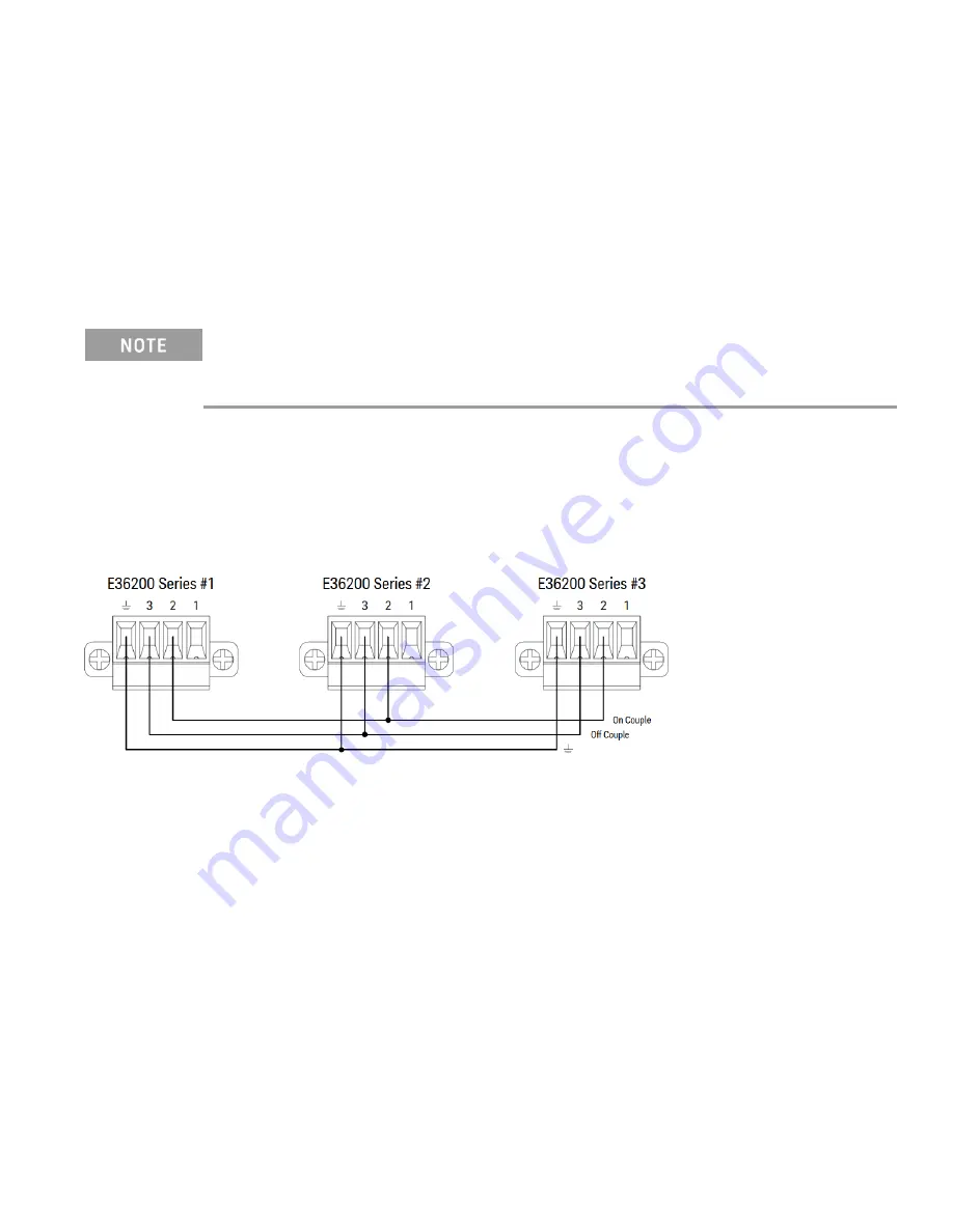
The digital connector pins of the synchronized power supplies that contain coupled outputs must be connected
together as shown in the following figure. In this example, pin 2 will be configured as the output On control. Pin 3
will be configured as the output Off control. The ground or Common pins also need to be connected together.
Only two of the digital connector pins on each power supply can be configured as “On Couple” and “Off Couple” on
each synchronized power supply. The designated pins will function as both an input and an output, with a negative
transition on one pin providing the synchronization signal to the other pins.
From the front panel:
1. Press
Utilities
>
I/O Config
>
Digital IO
to access the Digital I/O window.
2. Press
Pin 2
. Press
Function
and select
Couple On
.
3. Press
Pin 3
. Press
Function
and select
Couple Off
.
4. Repeat these steps for power supply #2 and #3.
Keysight E36200 Series User's Guide
87


