Pin functions
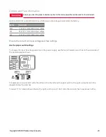
The following table describes the possible pin configuration for the digital port functions. For a complete description
of the electrical characteristics of the digital I/O port, refer to the product data sheet.
Pin function
Available configurable pins
Digital I/O and Digital In
Pins 1 through 3
External Trigger In/Out
Pins 1 through 3
Fault Out
Pin 1 and Pin 2
Inhibit In
Pin 3
Output Coupling
Pins 1 through 3
Common
Pin 4
In addition to the configurable pin functions, the active signal polarity for each pin is also configurable. When
Positive polarity is selected, a logical true signal is a voltage high at the pin. When Negative polarity is selected, a
logical true signal is a voltage low at the pin.
For more information on configuring the digital port functions, refer to
Using the Digital Control Port
Keysight E36300 Series User's Guide
37

