Disassembly
Tools required
Items
Torque value
PZ1 driver
9.0 in.lbs
T10 Torx driver
9.0 in.lbs
T8 Torx driver
9.0 in.lbs
1/4" nut socket
9.0 in.lbs
1/2" nut socket
3.5 in.lbs
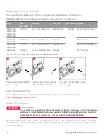
Removing/Installing the GPIB module (E36312A and E36313A only)
TURN OFF POWER AND REMOVE ALL CONNECTIONS BEFORE PROCEED
Turn off the power and remove all connections, including the power cord, from the instrument prior install-
ation/removal of the GPIB interface.
RETAIN GPIB COVER PLATE
After installing the GPIB option, retain the cover plate for use in the event that you ever remove the GPIB
option. The instrument should never be connected to power or inputs on the output terminals without either
the GPIB module or the cover plate securely covering the rear-panel opening.
Make sure you turn the power supply upside down before proceeding.
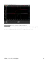
Steps Instructions
Visual
1.
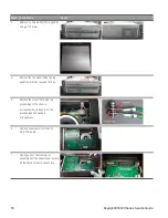
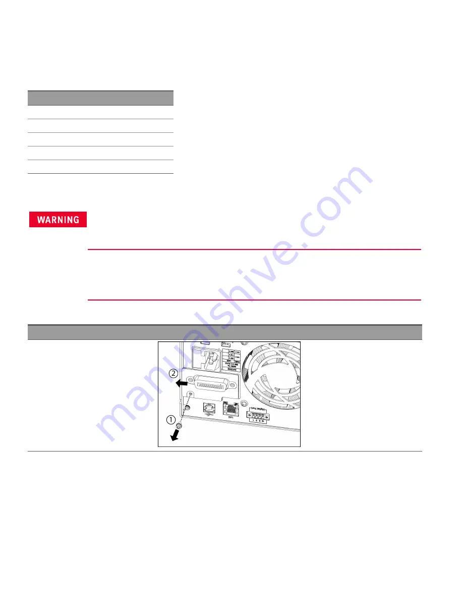
Remove the screw from the GPIB
module plate using a T10 driver.
Retain the screw for use later in this
procedure.
Then, remove the GPIB module by
sliding it to the left.
16
Keysight E36300 Series Service Guide

