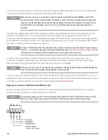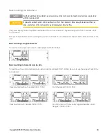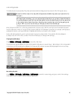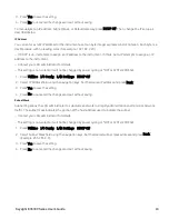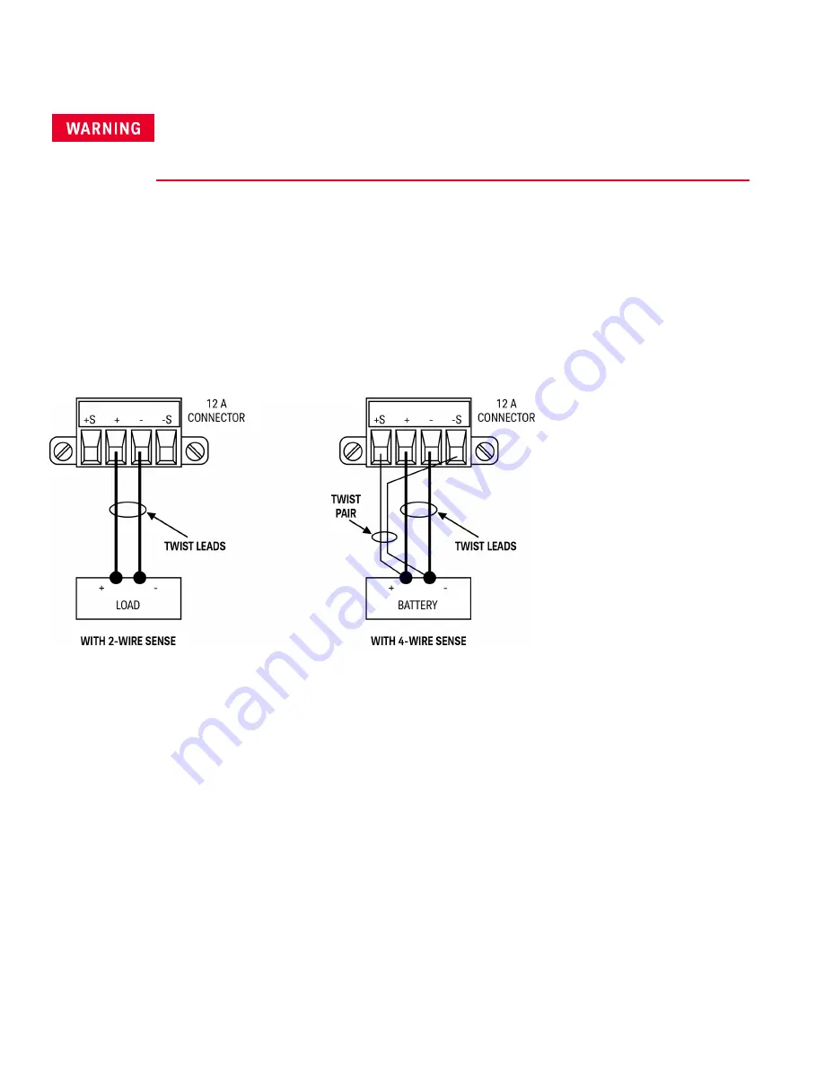
4-wire sense connection (E36312A and E36313A only)
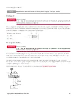
SHOCK HAZARD
Turn off AC power before making rear panel connections. All wires and straps must be properly connected
with the terminal block screws securely tightened
The power supply includes built-in relays that connect or disconnect the ± sense terminals from their corresponding
± output terminals. As shipped, the sense terminals are internally connected to the output terminals. This is referred
to as 2-wire, or local sensing.
4-wire, or remote sensing improves the voltage regulation at the load by monitoring the voltage at the load rather
than at the output terminals. This automatically compensates for the voltage drop in the load leads, which is
especially useful for CV operation with load impedance that vary or have significant lead resistance. Because remote
sensing is independent of other power supply functions, it can be used regardless of how the instrument is
programmed. Remote sensing has no effect during CC operation
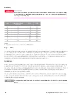
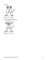
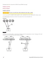
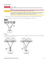
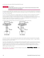
The following figures illustrate load connections using 2-wire sensing and 4-wire sensing.
Connect the load to the output terminals using separate connecting wires. Keep the wire-pair as short as possible
and twist or bundle it to reduce lead inductance and noise pickup. Keep the load leads under 14.7 meters (50 feet)
per lead because of inductance effects.
Connect the sense leads as close to the load as possible. Do NOT bundle the sense wire-pair together with the load
leads; keep the load wires and sense wires separate. The sense leads carry only a few milliamperes of current and can
be a lighter gauge than the load leads. However, any voltage drop in the sense leads can degrade the voltage
regulation of the instrument. Try to keep the sense lead resistance less than about 0.5 Ω per lead (this requires 20
AWG or heavier for a 50 foot length).
After turning the unit on, activate 4-wire remote voltage sensing by pressing
Source Settings
>
Sense 4w
. Refer to
Specifying 2-Wire or 4-Wire Sense
.
32
Keysight E36300 Series User's Guide

