background image

7

Characteristics and Specifications

Supplemental Characteristics

172

E3632A User’s Guide

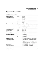
Maximum input power

500 VA with full load

Output voltage overshoot

[4]

1 V

Programming language

SCPI (Standard Commands for Programmable Instruments)

State storage memory

Three user-configurable stored states

Recommended calibration interval

1 year

[1] Maximum change in the output or readback per 

C after a 30-minute warm-up.

[2] Following a 30-minute warm-up, with the output in the ON state according to the operating mode (CC with load or CV), and 

with a change in the output over 8 hours under constant load, line, and ambient temperature.

[3] Maximum time required for output voltage to settle within 1% of its total excursion (for resistive load). Excludes command 

processing time.

[4] During turn-on or turn-off of the AC power, if the output control is set to less than 1 V. If the output control is set to 1 V or 

higher, there is no overshoot.

Table 7-3

Supplemental characteristics (continued)

Summary of Contents for E3632A

Page 1: ...Keysight E3632A DC Power Supply User s Guide ...

Page 2: ......

Page 3: ......

Page 4: ...ct with these terms the warranty terms in the separate agreement shall control Technology Licenses The hardware and or software described in this document are furnished under a license and may be used or copied only in accor dance with the terms of such license Restricted Rights Legend U S Government Restricted Rights Soft ware and technical data rights granted to the federal government include on...

Page 5: ...s manual for specific Warning or Caution information In position of a bi stable push control DC Direct current or voltage Terminal is at earth potential Used for measurement and control circuits designed to be operated with one terminal at earth potential AC Alternating current or voltage Positive binding post Protective conductor terminal Negative binding post Out position of a bi stable push con...

Page 6: ...afety standards for design manufacture and intended use of the instrument Keysight Technologies assumes no liability for the customer s failure to comply with these requirements CAUTION Use the device with the cables provided with the shipment If the device is used in a manner not specified by the manufacturer the device protection may be impaired Always use a dry cloth to clean the device Do not ...

Page 7: ... damaged or defective REMOVE POWER and do not use the device until safe operation is verified by service trained personnel If necessary return the device to Keysight for service and repair to ensure that the safety features are maintained Do not operate the device around flammable gases or fumes vapor or wet environments Observe all markings on the device before connecting any wiring to the device...

Page 8: ...1 EN 61010 1 2001 Canada CAN CSA C22 2 No 61010 1 04 USA ANSI UL 61010 1 2004 Environmental Conditions This instrument is designed for indoor use and in an area with low condensation The table below shows the general environmental requirements for this instrument Environmental condition Requirements Temperature Operating condition 0 C to 40 C full rated output Storage condition 20 C to 70 C Humidi...

Page 9: ...reil ISM est confomre a la norme NMB 001 du Canada This instrument complies with the WEEE Directive 2002 96 EC marking requirement This affixed product label indicates that you must not discard this electrical or electronic product in domestic household waste The CSA mark is a registered trademark of the Canadian Standards Association This symbol indicates the time period during which no hazardous...

Page 10: ...cal or electronic product in domestic household waste Product Category With reference to the equipment types in the WEEE directive Annex 1 this instrument is classified as a Monitoring and Control Instrument product The affixed product label is as shown below Do not dispose in domestic household waste To return this unwanted instrument contact your nearest Keysight Service Center or visit www keys...

Page 11: ...y DoC for this instrument is available on the Keysight Web site You can search the DoC by its product model or description at the Web address below http www keysight com go conformity NOTE If you are unable to search for the respective DoC contact your local Keysight representative ...

Page 12: ...X E3632A User s Guide THIS PAGE HAS BEEN INTENTIONALLY LEFT BLANK ...

Page 13: ... 11 Input power requirements 13 Rack mount the power supply 16 Product at a Glance 18 Front panel 18 Rear panel 21 Display annunciators 22 Operating the Power Supply 24 Cooling 24 Bench operation 24 Cleaning 24 2 Operation and Features Overview 26 Constant Voltage Operation 28 Front panel operation 28 Remote interface operation 30 Constant Current Operation 30 Front panel operation 30 Remote inter...

Page 14: ...Remote Voltage Sensing 41 CV regulation 41 Output rating 42 Output noise 42 Stability 42 Remote voltage sensing connections 43 Disabling the Output 44 Front panel operation 44 Remote interface operation 44 Disconnecting the output using an external relay 45 Knob locking 45 System Related Operations 46 Self test 46 Error conditions 47 Display control 48 Firmware revision query 49 SCPI language vers...

Page 15: ...63 Calibration security 63 To unsecure for calibration 64 To secure against calibration 65 To change the security code 66 Calibration count 67 Calibration message 68 3 Remote Interface Reference SCPI Command Summary 70 Introduction to the SCPI Language 74 Command format used in this manual 75 Command separators 76 Using the MIN and MAX parameters 77 Querying parameter settings 77 SCPI command term...

Page 16: ...Interface Commands 106 SCPI Status Registers 107 What is an event register 107 What is an enable register 107 SCPI status system 108 The Questionable Status register 109 The Standard Event register 110 The Status Byte register 112 Using Service Request SRQ and Serial POLL 113 Using STB to read the Status Byte 114 Using the Message Available Bit MAV 114 To interrupt your bus controller using SRQ 11...

Page 17: ...Front panel operation 128 Remote interface operation 129 Execution Error Messages 130 Self Test Error Messages 135 Calibration Error Messages 137 5 Application Programs Overview 140 Example Program for C GPIB IEEE 488 141 Example Program for Excel 5 0 Windows 3 1 and GPIB 144 6 Tutorial Overview of the Power Supply Operation 150 Output Characteristics 152 Unregulated state 154 Unwanted signals 154...

Page 18: ...e Voltage Range and Current Range 162 Series connections 162 Parallel connections 163 Remote Programming 164 Reliability 166 7 Characteristics and Specifications Physical Characteristics 168 Environmental Characteristics 169 Electrical Specifications 169 Supplemental Characteristics 171 ...

Page 19: ...rial connection 60 Figure 3 1 SCPI status system 108 Figure 6 1 Diagram of a simple series power supply with tap selection 150 Figure 6 2 Block diagram of the power supply showing the remote interface isolation 151 Figure 6 3 Ideal constant voltage power supply 152 Figure 6 4 Ideal constant current power supply 152 Figure 6 5 Output characteristics 153 Figure 6 6 Simplified diagram of the common m...

Page 20: ...XVIII E3632A User s Guide THIS PAGE HAS BEEN INTENTIONALLY LEFT BLANK ...
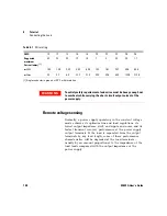
Page 21: ... 3 4 Bit definitions Questionable Status register 109 Table 3 5 Bit definitions Standard Event register 110 Table 3 6 Bit definitions Status Byte summary register 112 Table 3 7 SCPI confirmed commands 122 Table 3 8 Non SCPI commands 124 Table 4 1 Execution error messages 130 Table 4 2 Self test error messages 135 Table 4 3 Calibration error messages 137 Table 6 1 Wire rating 158 Table 6 2 Slew rat...

Page 22: ...XX E3632A User s Guide THIS PAGE HAS BEEN INTENTIONALLY LEFT BLANK ...

Page 23: ...roduction 2 Standard Shipped Items 7 Preparing the Power Supply 9 Product at a Glance 18 Operating the Power Supply 24 This chapter guides you to set up your power supply for the first time An introduction to all the features of the power supply is also given ...

Page 24: ...asy to use knob control settings Highly visible vacuum fluorescent display meters High accuracy and high resolution Remote voltage sensing Overvoltage and overcurrent protection Output on off Excellent load and line regulation and low ripple and noise Operating states storage Portable ruggedized case with non skid feet Flexible system features GPIB IEEE 488 and RS 232 interfaces are standard SCPI ...

Page 25: ...tage CV or constant current CC operation Overvoltage protection OVP and overcurrent protection OCP Three storage locations 1 to 3 for user defined operating states Automatic power on self test Remote sensing for load voltage User calibration from the front panel or via the remote interfaces Front panel operations Easy to use knob control Output range selection Enabling or disabling OVP and OCP fea...

Page 26: ...tax error detection Complete self test The front panel Vacuum Fluorescent Display VFD includes Displaying actual values of output voltage and current meter mode Or displaying the limit values of voltage and current limit mode Checking the operating status from the annunciators Checking the type of error from the error codes messages Connections to the power supply s output and to chassis ground ar...

Page 27: ...an be floated to maximum of 240 Vdc provided that the metal shorting bars without insulation are either replaced with insulated conductors or they are removed from the terminals so there is no operator access to the output conductors without insulation All field wiring insulation must be adequate for the voltage present ...

Page 28: ... directly or with a controller over the GPIB or RS 232 interface using calibration commands Correction factors are stored in non volatile memory and are used during output programming Calibration from the front panel or a controller eliminates the need to remove the top cover or even the need to remove the power supply from your system cabinet You can guard against unauthorized calibration by usin...

Page 29: ...rmine which power line voltage is selected at the factory The standard unit is configured for 115 Vac 10 47 Hz to 63 Hz input voltage For more information about changing the power line voltage setting refer to Power line voltage selection on page 14 Table 1 1 E3632A options Option Description OEM 115 Vac 10 47 Hz to 63 Hz input voltage OE3 230 Vac 10 47 Hz to 63 Hz input voltage OE9 100 Vac 10 47 ...

Page 30: ...ted below may be ordered from your local Keysight Sales Office either with the power supply or separately Table 1 2 E3632A accessories Part number Description 10833A GPIB cable 1 m 3 3 ft 10833B GPIB cable 2 m 6 6 ft 34398A RS 232 9 pin f to 9 pin f 2 5 m 8 2 ft cable 9 pin f to 25 pin m adapter ...

Page 31: ...lled The correct fuse is installed for your country when the power supply is shipped from the factory For 100 Vac or 115 Vac operation you must use a 4 AT fuse For 230 Vac operation you must use a 2 5 AT fuse 3 Connect the power line cord and turn on your power supply The front panel display will light up and a power on self test occurs automatically when you turn on the power supply NOTE Refer to...

Page 32: ...his is not the first time the power supply is turned on a different interface RS 232 or a different GPIB address may appear 3 The 15V OVP OCP and OFF annunciators are on All others are off The power supply will go into the power on reset state the output is disabled the OFF annunciator turns on the 15 V 7 A range is selected the 15V annunciator turns on and the knob is selected for voltage control...

Page 33: ...e power on reset state the output is disabled the OFF annunciator turns on the 15 V 7 A range is selected the 15V annunciator turns on and the knob is selected for voltage control 2 Enable the outputs The OFF annunciator turns off and the 15V OVP OCP and CV annunciators are lit The blinking digit can be adjusted by turning the knob Notice that the display is in the meter mode Meter mode means that...

Page 34: ...the OFF annunciator turns on the 15 V 7 A range is selected the 15V annunciator turns on and the knob is selected for voltage control 2 Connect a short across the and output terminals with an insulated test lead 3 Enable the output The OFF annunciator turns off and the 15V OVP and OCP annunciators are lit The CV or CC annunciator turns on depending on the resistance of the test lead The blinking d...

Page 35: ...ding to the instructions as shown in Power line voltage selection on page 14 Power line cord The power supply is shipped from the factory with a power line cord that has a plug appropriate for your location Contact the nearest Keysight Sales and Service Office if the wrong power line cord is included with your power supply Your power supply is equipped with a 3 wire grounding type power cord where...

Page 36: ...r and power line fuse on the power line module of the rear panel To change the power line voltage proceed as follows 1 Remove the power cord Remove the fuse holder assembly with a flat blade screwdriver from the rear panel 2 Install the correct line fuse Remove the power line voltage selector from the power line module 100 Vac or 115 Vac 4 AT fuse 230 Vac 2 5 AT fuse Power line voltage selector ...

Page 37: ...otate the power line voltage selector until the correct voltage appears 4 Replace the power line voltage selector and the fuse holder assembly in the rear panel 100 Vac 115 Vac or 230 Vac NOTE Verify that the correct line voltage is selected and the power line fuse is good ...

Page 38: ...g kit for a single instrument is available as Option 1CM 5063 9243 Installation instructions and hardware are included with each rack mounting kit Any Keysight System II instrument of the same size can be rack mounted beside the Keysight E3632A power supply 1 Remove the front and rear bumpers before rack mounting the power supply 2 To rack mount a single instrument order the adapter kit 5063 9243 ...

Page 39: ...r s Guide 17 3 To rack mount two instruments of the same depth side by side order the lock link kit 5061 9694 and rack mount kit 5063 9212 4 To install two instruments in a sliding support shelf order the support shelf 5063 9256 and the slide kit 1494 0015 ...

Page 40: ...ont panel Figure 1 2 Front panel Table 1 3 Front panel overview No Item Description 1 15 V 7 A range selection key Select the 15 V 7 A range and allow the full rated output to 15 V 7 A 2 30 V 4 A range selection key Select the 30 V 4 A range and allow the full rated output to 30 V 4 A ...

Page 41: ...must be unsecured before performing calibration Refer to the Service Guide E3632 90010 for more details on calibration 9 I O Configuration Secure key 3 Configure the power supply for remote interfaces or secure or unsecure the power supply for calibration Refer to the Service Guide E3632 90010 for more details on how to secure or unsecure the power supply 10 Output On Off key Enable or disable the...

Page 42: ...imit times out press again 4 Set the knob to current control mode using the voltage current adjust selection key 5 Move the blinking digit to the appropriate position using the resolution selection keys and change the blinking digit value to the desired current limit by turning the control knob 6 Press to enable the output After about five seconds the display will go to output monitoring mode auto...

Page 43: ...r s Guide 21 Rear panel Figure 1 4 Rear panel Table 1 4 Rear panel overview No Description 1 Power line voltage setting 2 Power line fuse holder assembly 3 AC inlet 4 Power line module 5 GPIB IEEE 488 interface connector 6 RS 232 interface connector ...

Page 44: ... Rmt The power supply is in the remote interface mode 15 V Shows the 15 V 7 A range is selected 30 V Shows the 30 V 4 A range is selected OVP The overvoltage protection function is enabled when the annunciator turns on or the overvoltage protection circuit has caused the power supply to shut down when the annunciator flashes OCP The overcurrent protection function is enabled when the annunciator t...

Page 45: ...efer to System Related Operations on page 46 for more information Unreg The output of the power supply is unregulated output is neither CV nor CC CV The power supply is in the constant voltage mode CC The power supply is in the constant current mode Table 1 5 Display annunciators overview continued Item Description NOTE To review the display annunciators hold down as you turn on the power supply D...

Page 46: ... air through the sides and exhausting it out the back Using a Keysight rack mount will not impede the flow of air Bench operation Your power supply must be installed in a location that allows sufficient space at the sides and rear of the power supply for adequate air circulation The rubber bumpers must be removed for rack mounting Cleaning No cleaning is required for this product If you wish to re...

Page 47: ...tates 33 Programming the Overvoltage Protection 35 Programming the Overcurrent Protection 38 Remote Voltage Sensing 41 Disabling the Output 44 System Related Operations 46 Remote Interface Configuration 51 GPIB Interface Configuration 56 RS 232 Interface Configuration 57 Calibration 63 This chapter describes the operations and features for the E3632A DC power supply ...

Page 48: ... 15 V 7 A or 30 V 4 A This feature allows more voltage at a lower current or more current at a lower voltage The desired output range is selected from the front panel or over the remote interfaces The 15V or 30V annunciator indicates the presently selected range When you press the Limit annunciator flashes the display of the power supply goes to the limit mode and the present limit values will be ...

Page 49: ...le the power supply is operating in CV mode in the 15 V 7 A range and controlled from the front panel then the CV and 15V annunciators will turn on If however the power supply is remotely controlled the Rmt annunciator will also turn on and when the power supply is being addressed over GPIB interface the Adrs annunciator will turn on Refer to Display annunciators on page 22 for more information ...

Page 50: ...pply in the 30 V 4 A range press before proceeding to the next step The 30V annunciator turns on 3 Set the display to the limit mode Notice that the Limit annunciator flashes indicating that the display is in the limit mode When the display is in the limit mode you can see the voltage and current limit values of the power supply Power 30V 4A Display Limit NOTE In the constant voltage mode the volt...

Page 51: ...urn to the meter mode Notice that the Limit annunciator turns off and the display shows the OUTPUT OFF message 7 Enable the output The OFF annunciator turns off and the 15V or 30V OVP OCP and CV annunciators are lit Notice that the display is in the meter mode In the meter mode the display shows the actual output voltage and current Refer to Programming the Overvoltage Protection on page 35 and Pr...

Page 52: ... disabled the OFF annunciator turns on the 15 V 7 A range is selected the 15V annunciator turns on and the knob is selected for voltage control To operate the power supply in the 30 V 4 A range press before proceeding to the next step The 30V annunciator turns on NOTE During actual CV operation if a load change causes the current limit to be exceeded the power supply will automatically cross over ...

Page 53: ...et the knob for current control The first digit of the ammeter will be flashing Change the flashing digit using the resolution selection keys and adjust the knob to the desired output current 6 Return to the meter mode Press or let the display time out after several seconds to return to the meter mode Notice that the Limit annunciator turns off and the display shows the OUTPUT OFF message Display ...

Page 54: ...he OVP and OCP annunciators 8 Verify that the power supply is in the constant current mode If you operate the power supply in the constant current CC mode verify that the CC annunciator is lit If the CV annunciator is lit choose a higher voltage limit Remote interface operation Output On Off NOTE During actual CC operation if a load change causes the voltage limit to be exceeded the power supply w...

Page 55: ... how to store and recall an operating state Front panel operation Storing the operating state 1 Set up the power supply for the desired operating state The storage feature remembers output range selection the limit value settings of voltage and current output on off state OVP and OCP on off state and OVP and OCP trip levels 2 Turn on the storage mode Three memory locations numbered 1 2 and 3 are a...

Page 56: ...ely 1 second Recalling a stored state 1 Turn on the recall mode Memory location 1 will be displayed in the recall mode RECALL 1 This message appears on the display for approximately three seconds 2 Recall the stored operating state Turn the knob to the right to change the displayed storage location to 3 RECALL 3 If this setting is not followed within three seconds with the power supply returns to ...

Page 57: ...when the trip level is set to less than 3 V The following steps show how to set the OVP trip level how to check OVP operation and how to clear overvoltage condition Front panel operation Setting the OVP level and enable the OVP circuit 1 Turn on the power supply The power supply will go into the power on reset state the output is disabled the OFF annunciator turns on the 15 V 7 A range is selected...

Page 58: ...eck that the OVP annunciator turns on Checking the OVP operation To check OVP operation raise the output voltage to near the trip point Then very gradually increase the output by turning the knob until the OVP circuit trips This will cause the power supply output to drop to near zero the OVP annunciator to flash and the CC annunciator to turn on The OVP TRIPPED message also appears on the display ...

Page 59: ...ator will not flash any more The output will return to meter mode Remote interface operation or Over Voltage Display Limit Display Limit Over Voltage Over Voltage Over Voltage Over Voltage Over Voltage Over Voltage VOLT PROT voltage MIN MAX Set the OVP level VOLT PROT STAT OFF ON Disable or enable the OVP circuit VOLT PROT CLE Clear the tripped OVP circuit NOTE The power supply s OVP circuit conta...

Page 60: ...level It is accomplished by programming the output current to zero The following steps show how to set the overcurrent protection trip level how to check OCP operation and how to clear overcurrent condition Front panel operation Setting the OCP level and enable the OCP circuit 1 Turn on the power supply The power supply will go into the power on reset state the output is disabled the OFF annunciat...

Page 61: ...D message is displayed for a second to show that the new OCP trip level is now in effect If the OCP settings are not changed NO CHANGE will be displayed The power supply will exit the OCP menu and the display will return to the meter mode Check that the OCP annunciator turns on Checking the OCP operation To check OCP operation raise the output current to near the trip point Then very gradually inc...

Page 62: ...nt level below the OCP trip point after pressing or raise the OCP trip level by using the knob after pressing 2 Move to the clear mode OCP ON You will see the above message after pressing If you changed the output voltage level press the twice Turn the knob to the right until the OCP CLEAR message appears on the display 3 Clear the overcoltage condition and exit this menu Now when you press again ...

Page 63: ...p in applications with long lead lengths as well as to accurately read back the voltage directly across the load When the power supply is connected for remote sensing the OVP circuit senses the voltage at the sensing points load and not the output terminals CV regulation The voltage load regulation specification in Chapter 7 applies at the output terminals of the power supply When remote sensing a...

Page 64: ...rsely affect the voltage load regulation Twist the sense leads to minimize external noise pickup and run them parallel and close to the load leads In noisy environments it may be necessary to shield the sense leads Ground the shield at the power supply end only Do not use the shield as one of the sense conductors Stability Using remote sensing under certain combinations of load lead lengths and la...

Page 65: ...terminals to the load as shown in Figure 2 2 Observe polarity when connecting the sensing leads to the load Notice that the metal shorting bars should be removed from the output and sense terminals for remote voltage sensing connections Figure 2 2 Remote voltage sensing connections NOTE For local voltage sensing connections the sense leads must be connected to the output terminals During remote se...

Page 66: ...memory the output is always disabled when power has been off or after a remote interface reset Front panel operation You can disable the output by pressing This key toggles between output Off and On states Remote interface operation NOTE While the output is disabled the range selection keys the control knob resolution selection keys and adjust selection key are still working If the display is in t...

Page 67: ...y state is ON the TTL output of pin 1 is high 4 5 V and pin 9 is low 0 5 V The levels are reversed when the OUTPut RELay state is OFF Knob locking The knob locking function can be used to disable the knob thereby preventing any unwanted changes during an experiment or when you leave the power supply unattended To disable the knob press the resolution selection key until the blinking digit disappea...

Page 68: ...ils the ERROR annunciator turns on A complete self test performs a series of tests and takes approximately two seconds to execute If all tests pass you can have a high confidence that the power supply is operational If the complete self test is successful PASS is displayed on the front panel If the self test fails FAIL is displayed and the ERROR annunciator turns on See the Service Guide E3632 900...

Page 69: ...y over the remote interface the last error stored in the queue the most recent error is replaced with 350 Queue overflow No additional errors are stored until you remove errors from the queue If no errors have occurred when you read the error queue the power supply responds with 0 No error over the remote interface or NO ERRORS from the front panel The error queue is cleared when power has been of...

Page 70: ...n display a message on the front panel by sending a command from the remote interface The power supply can display up to 12 characters of the message on the front panel any additional characters are truncated Commas periods and semicolons share a display space with the preceding character and are not considered individual characters When a message is displayed outputs are not sent to the display S...

Page 71: ...arated by commas and the fourth field is a revision code which contains three numbers The first number is the firmware revision number for the main processor the second is for the input output processor and the third is for the front panel processor Remote interface operation IDN The above command returns a string in the form HEWLETT PACKARD E3632A 0 X X X X X X Be sure to dimension a string varia...

Page 72: ...u can query the SCPI version from the remote interface only Remote interface operation Returns a string in the form of YYYY V where the Y represents the year of the version and the V represents the version number for that year for example 1995 0 SYST VERS Query the SCPI version ...

Page 73: ...nterface can be selected from the front panel only The interface selection is stored in non volatile memory and does not change when power has been off or after a remote interface reset If you select the GPIB interface you must select a unique address for the power supply The current address is displayed momentarily on the front panel when you turn on the power supply 1 Your GPIB bus controller ha...

Page 74: ...ce reset Your GPIB bus controller has its own address Be sure to avoid the bus controller s address for any instrument on the interface bus Keysight controllers generally use address 21 Baud rate selection RS 232 You can select one of six baud rates for RS 232 operation The rate is set to 9600 baud when the power supply is shipped from the factory The baud rate can be set from the front panel only...

Page 75: ... or after a remote interface reset To set the GPIB address To configure the power supply for the GPIB interface proceed as follows 1 Turn on the remote configuration mode HPIB 488 You will see the above message on the front panel display if the power supply has not been changed from the factory setting If RS 232 appears choose HPIB 488 by turning the knob to the right 2 Move to the GPIB address se...

Page 76: ...ation mode HPIB 488 You will see the above message on the display if the power supply has not been changed from the factory setting Notice that if you changed the remote interface selection to RS 232 before RS 232 message will be displayed 2 Choose the RS 232 interface RS 232 You can choose the RS 232 interface by turning the knob to the left 3 Move to the RS 232 interface setting mode and select ...

Page 77: ...etting the number of the data bits 5 Save the change and turn off the I O configuration mode CHANGE SAVED The RS 232 baud rate and parity selections are stored in non volatile memory and does not change when power has been off or after a remote interface reset The power supply displays a message to show that the change is now in effect If the baud rate and the parity are not changed NO CHANGE will...

Page 78: ...iguration star linear or both as long as the following rules are observed The total number of devices including the computer is not more than 15 The total length of all the cables used is not more than 2 m times the number of devices connected together up to a maximum of 20 m Do not stack more than three connector blocks together on any GPIB connector Make sure that all connectors are fully seated...

Page 79: ... information to help you use the power supply over the RS 232 interface The programming commands for RS 232 are explained in RS 232 Interface Commands on page 106 RS 232 configuration overview Configure the RS 232 interface using the parameters shown below Use at the front panel to select the baud rate parity and number of data bits refer to To set the baud rate and parity RS 232 on page 54 for mo...

Page 80: ...s and terminals are DTE Data Terminal Equipment devices Since the power supply is also a DTE device you must use a DTE to DTE interface cable These cables are also called null modem modem eliminator or crossover cables The interface cable must also have the proper connector on each end and the internal wiring must be correct Connectors typically have nine pins DB 9 connector or 25 pins DB 25 conne...

Page 81: ...le Kit This cable has a 9 pin female connector on each end The cable pin diagram is shown in Figure 2 4 Figure 2 4 DB 9 serial connection DB 25 serial connection If your computer or terminal has a 25 pin serial port with a male connector use the null modem cable and 25 pin adapter included with the Keysight 34398A Cable Kit The cable and adapter pin diagram are shown in Figure 2 5 Instrument PC DB...

Page 82: ...before the power supply will accept data from the interface When the power supply sets the DTR line FALSE the data must cease within 10 characters To disable the DTR DSR handshake do not connect the DTR line and tie the DSR line to logic TRUE If you disable the DTR DSR handshake also select a slower baud rate to ensure that the data is transmitted correctly Instrument PC DB9 Male DB9 Female DB9 Fe...

Page 83: ...erminate the command string After the response has been output the power supply sets the DTR line TRUE again unless the first case see above prevents this The power supply monitors the DSR line to determine when the bus controller is ready to accept data over the interface The power supply monitors the DSR line pin 6 on the RS 232 connector before each character is sent The output is suspended if ...

Page 84: ...a bits Make sure that your computer is set up for one start bit and two stop bits these values are fixed on the power supply Make sure to execute the SYSTem REMote command to place the power supply in the remote mode Verify that you have connected the correct interface cable and adapters Even if the cable has the proper connectors for your system the internal wiring may be incorrect The Keysight 3...

Page 85: ...hange when power has been off or after a remote interface reset To secure the power supply from the remote interface the security code may contain up to 12 alphanumeric characters as shown below The first character must be a letter but the remaining characters can be letters or numbers You do not have to use all 12 characters but the first character must always be a letter A _ _ _ _ _ _ _ _ _ _ _ ...

Page 86: ...e enter the security code using the knob and resolution selection keys and then press 3 Save the change and exit the menu UNSECURED When you press to save the change you will see the message above for one second if the security code is correct The unsecured setting is stored in non volatile memory and does not change when power has been off or after a remote interface reset To exit the calibration...

Page 87: ...s set to HP003632 Read the security code rules at Calibration security on page 63 before attempting to secure the power supply Front panel operation 1 Select the calibration mode UNSECURED If the power supply is unsecured you will see the above message for one second by holding for five seconds when you turn on the power supply 2 Enter the security code 000000 CODE To secure the power supply press...

Page 88: ...L SEC STAT ON HP003632 To change the security code To change the security code you must first unsecure the power supply and then enter a new code Read the security code rules at Calibration security on page 63 before attempting to secure the power supply Front panel operation To change the security code first make sure that the power supply is unsecured Press after the CAL MODE message is displaye...

Page 89: ...ts initial value The calibration count feature can be performed from the remote interface only The calibration count is stored in non volatile memory and does not change when power has been turned off or after a remote interface reset The calibration count increments up to a maximum of 32767 after which it wraps around to 0 Since the value increments by one for each calibration point a complete ca...

Page 90: ...to contact for a new calibration You can record and read information in the calibration message from the remote interface only The power supply should be unsecured before sending a calibration message The calibration message may contain up to 40 characters The calibration message is stored in non volatile memory and does not change when power has been off or after a remote interface reset Remote i...

Page 91: ...g the APPLy Command 83 Output Settings and Operation Commands 85 Triggering Commands 93 System Related Commands 96 Calibration Commands 102 RS 232 Interface Commands 106 SCPI Status Registers 107 Status Reporting Commands 117 Halting an Output in Progress 121 SCPI Conformance Information 122 IEEE 488 Conformance Information 125 This chapter lists the SCPI commands ...

Page 92: ... following conventions are used for the SCPI command syntax Square brackets indicate optional keywords or parameters Braces enclose parameters within a command string Triangle brackets indicate that you must substitute a value or a code for the enclosed parameter A vertical bar separates one of two or more alternative parameters NOTE If you are a first time user of the SCPI language refer to Intro...

Page 93: ...ent PROTection STATe 0 1 OFF ON CURRent PROTection STATe CURRent PROTection TRIPped CURRent PROTection CLEar VOLTage LEVel IMMediate AMPLitude voltage MIN MAX UP DOWN VOLTage LEVel IMMediate AMPLitude MIN MAX VOLTage LEVel IMMediate STEP INCRement numeric value DEFault VOLTage LEVel IMMediate STEP INCRement DEFault VOLTage LEVel TRIGgered AMPLitude voltage MIN MAX VOLTage LEVel TRIGgered AMPLitude...

Page 94: ...ON RELay STATe STATe OFF ON STATe IDN RST TST SAV 1 2 3 RCL 1 2 3 Calibration Commands CALibration COUNt CURRent DATA numeric value CURRent LEVel MIN MID MAX CURRent PROTection DAC ERRor SECure CODE new code SECure STATe OFF ON code SECure STATe STRing quoted string STRing VOLTage DATA numeric value VOLTage LEVel MIN MID MAX VOLTage PROTection RS 232 Interface Commands SYSTem LOCal REMote RWLock T...

Page 95: ...CONDition EVENt ENABle enable value ENABle SYSTem ERRor CLS ESE enable value ESE ESR OPC OPC PSC 0 1 PSC SRE enable value SRE STB WAI IEEE 488 Conformance Information CLS ESE enable value ESE ESR IDN OPC OPC PSC 0 1 PSC RST SAV 1 2 3 RCL 1 2 3 SRE enable value SRE STB TRG TST WAI Table 3 1 SCPI command summary continued ...

Page 96: ... hierarchical structure also known as a tree system In this system associated commands are grouped together under a common node or root thus forming subsystems A portion of the SOURce subsystem is shown below to illustrate the tree system SOURce CURRent current MIN MAX UP DOWN CURRent MIN MAX CURRent TRIGgered current MIN MAX TRIGgered MIN MAX VOLTage voltage MIN MAX UP DOWN VOLTage MIN MAX VOLTag...

Page 97: ... CURRENT curr and Curr are all acceptable Other forms such as CUR and CURREN will generate an error Braces enclose the parameter choices for a given command string The braces are not sent with the command string A vertical bar separates multiple parameter choices for a given command string Triangle brackets indicate that you must specify a value for the enclosed parameter For example the above syn...

Page 98: ...more than one parameter you must separate adjacent parameters using a comma as shown below SOURce CURRent TRIGgered APPLy 3 5 1 5 Command separators A colon is used to separate a command keyword from a lower level keyword as shown below SOURce CURRent TRIGgered A semicolon is used to separate two commands within the same subsystem and can also minimize typing For example sending the following comm...

Page 99: ...ue of most parameters by adding a question mark to the command For example the following command sets the output current to 5 A CURR 5 You can query the value by executing CURR You can also query the maximum or minimum value allowed with the present function as follows CURR MAX CURR MIN CAUTION If you send two query commands without reading the response from the first and then attempt to read the ...

Page 100: ...88 2 standard defines a set of common commands that perform functions like reset self test and status operations Common commands always begin with an asterisk are four to five characters in length and may include one or more parameters The command keyword is separated from the first parameter by a blank space Use a semicolon to separate multiple commands as shown below RST CLS ESE 32 OPC SCPI para...

Page 101: ... command uses discrete parameters TRIG SOUR BUS IMM Boolean parameters Boolean parameters represent a single binary condition that is either true or false For a false condition the power supply will accept OFF or 0 For a true condition the power supply will accept ON or 1 When you query a boolean setting the power supply will always return 0 or 1 The following command uses a boolean parameter DISP...

Page 102: ...r details on outputting command strings and entering data Using the APPLy command The APPLy command provides the most straightforward method to program the power supply over the remote interface For example the following statement executed from your computer will set the power supply to an output of 3 V rated at 1 A APPL 3 0 1 0 Using the low level commands Although the APPLy command provides the ...

Page 103: ...ger or an immediate internal trigger as a trigger source By default the BUS trigger source is selected If you want the power supply to use an immediate internal trigger you must select IMMediate For example the following statements executed from your computer will set to an output of 3 V 1 A immediately dimension statement Dimension string array 80 elements SYST ERR Read the error queue bus enter ...

Page 104: ...mming values available and the MINimum MAXimum DEFault and reset values of your power supply Refer to Table 3 2 to identify the programming values when programming the power supply Table 3 2 Keysight E3632A programming ranges 0 to 15 V 7 A range 0 to 30 V 4 A range Voltage Programming range 0 V to 15 45 V 0 V to 30 90 V MAX value 15 45 V 30 90 V MIN value 0 V DEFault value 0 V RST value 0 V Curren...

Page 105: ...PLy command changes the power supply s output to the newly programmed values only if the programmed values are valid within the presently selected range An execution error will occur if the programmed values are not valid within the selected range You can substitute MINimum MAXimum or DEFault in place of a specific value for the voltage and current parameters MIN selects the lowest values of 0 V a...

Page 106: ... current setting values and returns a quoted string The voltage and current are returned in sequence as shown in the sample string below the quotation marks are returned as part of the string 15 00000 4 00000 In the above string the first number 15 00000 is the voltage setting value and the second number 4 00000 is the current setting value ...

Page 107: ...y to the newly programmed value regardless of the output range presently selected You can substitute MINimum or MAXimum in place of a specific value for the current parameter MIN selects the lowest current values of 0 A MAX selects the highest current values allowed for the selected range This command also increases or decreases the immediate current level using the UP or DOWN parameter by a prede...

Page 108: ...or example the output current will increase or decrease 10 mA if the step size is 0 01 This command is useful when you program the power supply to the allowed minimum resolution At RST the step size is the value of the minimum resolution CURRent STEP DEFault This query returns the value of the step size currently specified The returned parameter is a numeric value DEFault gives the minimum resolut...

Page 109: ...RR TRIG MAX and CURR TRIG MIN return the highest and lowest programmable triggered current levels CURRent PROTection current MINimum MAXimum This command sets the current level at which the overcurrent protection OCP circuit will trip If the peak output current exceeds the OCP level then the output current is programmed to zero The Questionable Status register OC bit is set refer to SCPI status sy...

Page 110: ...s the overcurrent protection circuit to be cleared After this command the output current is restored to the state it was in before the current protection tripped and the OCP trip level remains unchanged to the value presently programmed Before sending this command lower the output current below the trip OCP point or raise the OCP trip level above the output setting VOLTage voltage MINimum MAXimum ...

Page 111: ... STEP numeric value DEFault This command sets the step size for voltage programming with the VOLT UP and VOLT DOWN commands To set the step size to the minimum resolution set the step size to DEFault The minimum resolution of the step size is approximately 0 55 mV The VOLT STEP DEF returns the minimum resolution of your instrument The immediate voltage level increases or decreases by the value of ...

Page 112: ...tage level presently programmed If no triggered level is programmed the VOLT level is returned VOLT TRIG MAX and VOLT TRIG MIN return the highest and lowest programmable triggered voltage levels VOLTage PROTection voltage MINimum MAXimum This command sets the voltage level at which the overvoltage protection OVP circuit will trip If the peak output voltage exceeds the OVP level then the power supp...

Page 113: ...p is removed At RST this value is set to ON VOLTage PROTection STATe This query returns the state of the overvoltage protection function The returned parameter is 0 OFF or 1 ON VOLTage PROTection TRIPped This query returns a 1 if the overvoltage protection circuit is tripped and not cleared or a 0 if not tripped VOLTage PROTection CLEar This command causes the overvoltage protection circuit to be ...

Page 114: ...ed the maximum programmable voltage and current are limited to 30 90 V and 4 12 A P30V or HIGH is the identifier for the 0 V 4 A range and P15V or LOW is for the 15 V 7 A range At RST the 15 V 7 A range is selected VOLTage RANGe This query returns the currently selected range The returned parameter is P30V HIGH or P15V LOW MEASure CURRent This query returns the current measured across the current ...

Page 115: ...ified trigger source and the start of any corresponding output change Notice that the time delay is valid for only the bus trigger source Finally you must provide an INITiate command If the IMMediate source is selected the selected output is set to the triggered level immediately But if the trigger source is the bus the power supply is set to the triggered level after receiving the Group Execute T...

Page 116: ...ted the power supply waits for all pending operations to complete before executing any additional commands For example the following command string guarantees that the first trigger is accepted and is executed before the second trigger is recognized TRIG SOUR BUS TRG WAI TRG WAI You can use the OPC operation complete query command or the OPC operation complete command to signal when the operation ...

Page 117: ...s MAX 3600 seconds At RST this value is set to 0 seconds TRIGger DELay MINimum MAXimum This query returns the trigger delay TRIGger SOURce BUS IMMediate Select the source from which the power supply will accept a trigger The power supply will accept a bus software trigger or an internal immediate trigger At RST the bus trigger source is selected TRIGger SOURce This query returns the present trigge...

Page 118: ...lay setting Returns 0 OFF or 1 ON DISPlay TEXT quoted string Display a message on the front panel The power supply will display up to 12 characters in a message any additional characters are truncated Commas periods and semicolons share a display space with the preceding character and are not considered individual characters DISPlay TEXT This query returns the message sent to the front panel and r...

Page 119: ... the TTL output of pin 1 is high 4 5 V and pin 9 is low 0 5 V The levels are reversed when the OUTPut RELay state is OFF At RST the OUTPut RELay state is OFF TTL output of pin 1 or pin 9 of the RS 232 connector is available only after installing two jumpers inside the power supply Refer to the Service Guide for more information OUTPut RELay This command returns the state of the TTL relay logic sig...

Page 120: ... beeps once each time an error is generated If more than 20 errors have occurred the last error stored in the queue the most recent error is replaced with 350 Queue overflow No additional errors are stored until you remove errors from the queue If no errors have occurred when you read the error queue the power supply responds with 0 No error The error queue is cleared when power has been off or af...

Page 121: ... first number is the firmware revision number for the main power supply processor the second is for the input output processor and the third is for the front panel processor The command returns a string with the following format be sure to dimension a string variable with at least 40 characters HEWLETT PACKARD E3632A 0 X X X X X X RST This command resets the power supply to its power on state as f...

Page 122: ...on in non volatile memory Three memory locations numbered 1 2 and 3 are available to store operating states of the power supply The state storage feature remembers the states or values of the following commands CURR CURR STEP CURR TRIG CURR PROT CURR PROT STAT DISP OUTP OUTP REL TRIG DEL TRIG SOUR VOLT VOLT STEP VOLT TRIG VOLT PROT VOLT PROT STAT and VOLT RANG To recall a stored state you must use...

Page 123: ...2 3 This command recalls a previously stored state To recall a stored state you must use the same memory location used previously to store the state NOTE DISP OFF ON can be stored and recalled in remote interface mode only Going to local mode automatically sets the display state to ON ...

Page 124: ...on point a complete calibration will increase the value by five counts CALibration CURRent DATA numeric value This command can only be used after calibration is unsecured and the output state is ON It enters a current value that you obtained by reading an external meter You must first select the minimum calibration level CAL CURR LEV MIN for the value being entered You must then select the middle ...

Page 125: ...tomatically performs the calibration and stores the new overcurrent constant in non volatile memory Notice that current calibration precedes before sending this command CALibration DAC ERRor This command corrects the differential nonlinearity error of the internal DAC without an external meter You must send this command before calibrating the voltage It takes about 30 seconds to execute the comman...

Page 126: ...ue This command can only be used after calibration is unsecured and the output state is ON It enters a voltage value that you obtained by reading an external meter You must first select the minimum calibration level CAL VOLT LEV MIN for the value being entered You must then select the middle and maximum calibration levels CAL VOLT LEV MID and CAL VOLT LEV MAX for the value being entered Three succ...

Page 127: ...the power supply It takes about seven seconds to execute the command The calibration must be unsecured and the output be opened before calibrating the overvoltage protection circuit The power supply automatically performs the calibration and stores the new overvoltage constant in non volatile memory Notice that voltage calibration precedes before sending this command ...

Page 128: ...he front panel except the Local key are disabled SYSTem RWLock This command places the power supply in the remote mode for RS 232 operation This command is the same as the SYST REM command except that all keys on the front panel are disabled including the Local key Ctrl C This command clears the operation in progress over the RS 232 interface and discards any pending output data This is equivalent...

Page 129: ...t is set subsequent state changes are ignored Bits in an event register are automatically cleared by a query of that register such as ESR or STAT QUES EVEN or by sending the CLS clear status command A reset RST or device clear will not clear bits in event registers Querying an event register returns a decimal value which corresponds to the binary weighted sum of all bits set in the register What i...

Page 130: ... Reference SCPI Status Registers 108 E3632A User s Guide SCPI status system Figure 3 1 SCPI status system 20 1 21 2 22 4 23 8 24 16 25 32 26 64 27 128 28 256 29 512 210 1024 211 2048 212 4096 213 8192 214 16384 215 32768 ...

Page 131: ...t 4 reports an overtemperature condition of the fan bit 9 reports that the overvoltage protection circuit has tripped and bit 10 reports that the overcurrent protection circuit has tripped To read the register send STATus QUEStionable The Questionable Status event register is cleared when you execute the CLS clear status command you query the event register using STAT QUES status questionable even...

Page 132: ...register To set the enable register mask you write a decimal value to the register using the ESE Event Status Enable command NOTE An error condition Standard Event register bit 2 3 4 or 5 will always record one or more errors in the power supply s error queue Read the error queue using the SYST ERR command Table 3 5 Bit definitions Standard Event register Bit Decimal value Definition 0 OPC 1 Opera...

Page 133: ...have previously configured the power supply using the PSC 1 command The enable register will not be cleared at power on if you have previously configured the power supply using the PSC 0 command 4 EXE 16 Execution Error An execution error occurred refer to error messages 211 to 223 in Execution Error Messages on page 130 5 CME 32 Command Error A command syntax error occurred refer to error message...

Page 134: ...yte summary register is cleared when you execute the CLS clear status command Querying the Standard Event register ESR command will clear only bit 5 in the Status Byte summary register For example 24 8 16 is returned when you have queried the status of the Status Byte register QUES and MAV conditions have occurred Table 3 6 Bit definitions Status Byte summary register Bit Decimal value Definition ...

Page 135: ...en bit 6 request service is set in the Status Byte an IEEE 488 service request interrupt message is automatically sent to the bus controller The bus controller may then poll the instruments on the bus to identify which one requested service the instrument with bit 6 set in its Status Byte To read the Status Byte summary register send the IEEE 488 serial poll message Querying the summary register w...

Page 136: ...ssible using the STB command Executing the STB command does not clear the Status Byte summary register Using the Message Available Bit MAV You can use the Status Byte Message Available bit bit 4 to determine when data is available to read into your bus controller The power supply subsequently clears bit 4 only after all messages have been read from the output buffer CAUTION The IEEE 488 standard d...

Page 137: ...Send a device clear message to clear the power supply s output buffer for example CLEAR 705 2 Clear the event registers with the CLS clear status command 3 Enable the Operation Complete bit bit 0 in the Standard Event register by executing the ESE 1 command 4 Send the OPC operation complete query command and enter the result to ensure synchronization 5 Execute your command string to program the de...

Page 138: ... sequence is completed This bit is set in the register after an OPC command has been executed If you send OPC after a command which loads a message in the power supply s output buffer query data you can use the Operation Complete bit to determine when the message is available However if too many messages are generated before the OPC command executes sequentially the output buffer will overload and...

Page 139: ... stored When you have read all errors from the queue the ERROR annunciator turns off The power supply beeps once each time an error is generated If more than 20 errors have occurred the last error stored in the queue the most recent error is replaced with 350 Queue overflow No additional errors are stored until you remove errors from the queue If no errors have occurred when you read the error que...

Page 140: ...ATus QUEStionable This command queries the Questionable Status event register The power supply returns a decimal value which corresponds to the binary weighted sum of all bits in the register These bits are latched Reading the event register clears it STATus QUEStionable ENABle enable value This command enables bits in the Questionable Status Enable register The selected bits are then reported to ...

Page 141: ... command sets the Operation Complete bit bit 0 of the Standard Event register after the command is executed OPC This command returns 1 to the output buffer after the command is executed PSC 0 1 Power on status clear This command clears the Status Byte and the Standard Event register enable masks when power is turned on PSC 1 When PSC 0 is in effect the Status Byte and Standard Event register enabl...

Page 142: ...is command queries the Status Byte summary register The STB command is similar to a serial poll but it is processed like any other instrument command The STB command returns the same result as a serial poll but the Request Service bit bit 6 is not cleared if a serial poll has occurred WAI This command instructs the power supply to wait for all pending operations to complete before executing any ad...

Page 143: ...lear over the GPIB interface using Keysight BASIC CLEAR 705 IEEE 488 device clear The following statement shows how to send a device clear over the GPIB interface using the GPIB Command Library for C or QuickBASIC IOCLEAR 705 NOTE For RS 232 operation sending the Ctrl C character will perform the same operation as the IEEE 488 device clear message The power supply s DTR data terminal ready handsha...

Page 144: ...ribed in this manual for simplicity or clarity Most of these non documented commands duplicate the functionality of a command already described in this manual SCPI confirmed commands Table 3 7 lists the SCPI confirmed commands that are used by the power supply Table 3 7 SCPI confirmed commands DISPlay WINDow STATe OFF ON WINDow STATe WINDow TEXT DATA quoted string WINDow TEXT DATA WINDow TEXT CLEa...

Page 145: ... IMMediate AMPLitude voltage MIN MAX UP DOWN VOLTage LEVel IMMediate AMPLitude MIN MAX VOLTage LEVel IMMediate STEP INCRement numeric value DEFault VOLTage LEVel IMMediate STEP INCRement DEFault VOLTage LEVel TRIGgered AMPLitude voltage MIN MAX VOLTage LEVel TRIGgered AMPLitude MIN MAX VOLTage PROTection LEVel voltage MIN MAX VOLTage PROTection LEVel MIN MAX VOLTage PROTection STATe 0 1 OFF ON VOL...

Page 146: ...andard in mind and they follow all of the command syntax rules defined by the standard Table 3 8 Non SCPI commands APPLy voltage DEF MIN MAX current DEF MIN MAX APPLy CALibration COUNt CURRent DATA numeric value CURRent LEVel MIN MID MAX CURRent PROTection DAC ERRor SECure CODE new code SECure STATe OFF ON code SECure STATe STRing quoted string STRing VOLTage DATA numeric value VOLTage LEVel MIN M...

Page 147: ...e Information Dedicated hardware lines Addressed commands ATN Attention IFC Interface Clear REN Remote Enable SRQ Service Request Enable DCL Device Clear EOI End or Identify GET Group Execute Trigger GTL Go to Local LLO Local Lockout SDC Selected Device Clear SPD Serial Poll Disable SPE Serial Poll Enable ...

Page 148: ...ce Reference IEEE 488 Conformance Information 126 E3632A User s Guide IEEE 488 2 common commands CLS ESE enable value ESE ESR IDN OPC OPC PSC 0 1 PSC RST SAV 1 2 3 4 5 RCL 1 2 3 4 5 SRE enable value SRE STB TRG TST WAI ...

Page 149: ...ser s Guide 4 Error Messages Overview 128 Execution Error Messages 130 Self Test Error Messages 135 Calibration Error Messages 137 This chapter lists the error messages that may appear as you are working with the power supply ...

Page 150: ... If more than 20 errors have occurred the last error stored in the queue the most recent error is replaced with 350 Queue overflow No additional errors are stored until you remove errors from the queue If no erros have occurred when you read the error queue the supply responds with 0 No error over the remote interface or NO ERRORS from the front panel The error queue is cleared when power has been...

Page 151: ... 4 Overview E3632A User s Guide 129 Remote interface operation Errors have the following format the error string may contain up to 80 characters 113 Undefined header SYSTem ERRor Reads one error from the error queue ...

Page 152: ...nk space or you may have used a blank space instead of a comma Example TRIG SOUR BUS or APPL 1 0 1 0 104 Data type error The wrong parameter type was found in the command string You may have specified a number where a string was expected or vice versa 105 GET not allowed A Group Execute Trigger GET is not allowed within a command string 108 Parameter not allowed More parameters were received than ...

Page 153: ...number specified for a parameter value Example ESE B01010102 123 Numeric overflow A numeric parameter was found whose exponent was larger than 32000 124 Too many digits A numeric parameter was found whose mantissa contained more than 255 digits excluding leading zeros 128 Numeric data not allowed A numeric parameter was received but a character string was expected Example DISP TEXT 123 130 1 Suffi...

Page 154: ... received Check to see if you have enclosed the character string in single or double quotes Example DISP TEXT ON 158 String data not allowed A character string was received but is not allowed for the command Check the list of parameters to verify that you have used a valid parameter type Example TRIG DEL zero 160 to 168 Block data errors The power supply does not accept block data 170 to 178 Expre...

Page 155: ...age 135 350 Queue overflow The error queue is full because more than 20 errors have occurred No additional errors are stored until you remove errors from the queue The error queue is cleared when power has been turned off or after a CLS clear status command has been executed 410 Query INTERRUPTED A command was received which sends data to the output buffer but the output buffer contained data from...

Page 156: ...ller U10 and the I O controller U752 511 RS 232 framing error 512 RS 232 overrun error 513 RS 232 parity error 514 Command allowed only with RS 232 There are three commands which are only allowed with the RS 232 interface SYSTem LOCal SYSTem REMote and SYSTem RWLock 521 Input buffer overflow 522 Output buffer overflow 550 Command not allowed in local You should always execute the SYSTem REMote com...

Page 157: ...lope counters A failure is detected when a sync interrupt is not recognized and subsequent time out occurs 604 A D slope convergence failed The input amplifier is configured to the measure zero MZ state in the 10 V range This test checks whether the ADC integrator produces nominally the same number of positive and negative slope decisions 10 during a 20 ms interval 605 Cannot calibrate rundown gai...

Page 158: ...unciator will be turned on 626 I O processor failed self test This test causes the earth referenced processor U4 U752 for serial MY53xx6xxx to execute an internal ram test Failure will generate an error 630 Fan test failed This test checks if the fan current is flowing If the current is not detected at power on self test the power supply will beep and the error annunciator will be turned on Fan te...

Page 159: ...rity code may contain up to 12 alphanumeric characters The first character must be a letter 704 Secure code too long A security code was received which contained more than 12 characters 705 Cal aborted A calibration in progress is aborted when you press any front panel key send a device clear or change the local remote state of the instrument 708 Cal output disabled Calibration is aborted by sendi...

Page 160: ...abled You must set both overvoltage and overcurrent protection status to OFF before and during the calibration 740 Cal checksum failed secure state 741 Cal checksum failed string data 742 Cal checksum failed store recall data in location 0 743 Cal checksum failed store recall data in location 1 744 Cal checksum failed store recall data in location 2 745 Cal checksum failed store recall data in loc...

Page 161: ...User s Guide 5 Application Programs Overview 140 Example Program for C GPIB IEEE 488 141 Example Program for Excel 5 0 Windows 3 1 and GPIB 144 This chapter contains two application programs that utilize the remote interface ...

Page 162: ...mands available to program the power supply All program examples have been tested on a PC with Windows 3 1 or Windows for Workgroups Both examples are for use with GPIB IEEE 488 These examples require a VISA Virtual Instrument Software Architecture driver with your GPIB PC card You should have the visa dll in your windows system directory for the GPIB examples to work All program examples perform ...

Page 163: ...h file to the lib and include development directory These are usually found at c vxipnp win lib msc and c vxipnp win include Diode c Diode C This example program steps the E3632A DC Power Supply through 10 voltages and measures the current response It prints the voltage step and the current response as a table Note that the GPIB address is the default address from the factory for the E3632A includ...

Page 164: ...n viScanf power_supply s reply_string printf Instrument identification string n s n n reply_string Initialize Power Supply viPrintf power_supply RST n Set power on condition viPrintf power_supply Current 2 n Set Current limit to 2A viPrintf power_supply Output on n Turn output on printf Voltage Current n n Print heading Step from 0 6v to 0 8 volt in 02volt steps for voltage 6 voltage 8001 voltage ...

Page 165: ..._supply Output Off n turn off output Close communication session viClose power_supply viClose defaultRM Pauses for a specified number of milliseconds void delay clock_t wait clock_t goal clock_t delay wait wait 1000 delay clock_t wait CLOCKS_PER_SEC goal delay clock while goal clock End of program ...

Page 166: ...b Create one more module named GPIB bas The module GPIB bas will set up all the overhead needed to talk to the GPIB port This module will subroutines that allow the communication in a simple form The macro called Diode is an example that tests a diode using the other module To try the example for characterizing a diode type in both modules Once the modules are completed go to a worksheet In cell A...

Page 167: ...and change the variable VISAaddr 5 to the required GPIB address Sub Diode Range B5 B15 ClearContents Dim I As Integer OpenPort SendSCPI RST Reset E3632A to power on condition SendSCPI Output ON Turn on the output For I 5 To 15 Convert the worksheet value to a string add to SCPI command SendSCPI Volt Str Cells I 1 Request a current measurement put response in worksheet Cells I 2 Val SendSCPI meas c...

Page 168: ...nager id for VISA GPIB Global vi As Long stores the session for VISA Dim errorStatus As Long VTL error code This routine requires the file VISA dll It typically resides under the directory c windows system This routine uses the VTL Library to send commands to an instrument A description of these and additional VTL commands are contained in the Hewlett Packard Visa Transition Library book Keysight ...

Page 169: ...trument for a response Exit Function VIerrorHandler Display the error message in the txtResponse TextBox MsgBox I O Error Error Close the device session errorStatus viClose vi Exit Function End Function Sub OpenPort Dim VISAaddr As String Change the GPIB address here VISAaddr 5 errorStatus viOpenDefaultRM videfaultRM open the visa session Open communication to instrument errorStatus viOpen videfau...

Page 170: ...5 Application Programs Example Program for Excel 5 0 Windows 3 1 and GPIB 148 E3632A User s Guide THIS PAGE HAS BEEN INTENTIONALLY LEFT BLANK ...

Page 171: ... Output Characteristics 152 Connecting the Load 157 Extending the Voltage Range and Current Range 162 Remote Programming 164 Reliability 166 This chapter describes the basic operation of a linear power supply and gives specific details on the operation and use of the E3632A DC power supply ...

Page 172: ... maintain a constant output voltage Because the variable resistance of Figure 6 1 is actually one or more power transistor operating in the linear class A mode supplies with this type of regulator are often called linear power supplies Linear power supplies have many advantages and usually provide the simplest most effective means of satisfying high performance and low power requirements Figure 6 ...

Page 173: ...y has a high reliability The Keysight E3632A contains a linear regulated power supply It is controlled by a control circuit that provides voltages to program the outputs The power supply sends back to the control circuits a voltage representing the output at the terminals The control circuits receive information from the front panel and send information to the display Similarly the control circuit...

Page 174: ...oltage power supply would have a zero output impedance at all frequencies Thus as shown in Figure 6 3 the voltage would remain perfectly constant in spite of any changes in output current demanded by the load Figure 6 3 Ideal constant voltage power supply Figure 6 4 Ideal constant current power supply ...

Page 175: ...egulated Figure 6 5 shows the operating modes of the output of the Keysight E3632A power supply The operating point of one supply will be either above or below the line RL RC This line represents a load where the output voltage and the output current are equal to the voltage and current setting When the load RL is greater than RC the output voltage will dominate since the current will be less then...

Page 176: ...C line voltage below the specifications The unregulated condition may occur momentarily For example when the output is programmed for a large voltage step the output capacitor or a large capacitive load will charge up at the current limit setting During the ramp up of the output voltage the power supply will be in the unregulated mode During the transition from CV to CC as when the output is short...

Page 177: ...age drop equal to the current flow multiplied by the impedance To minimize this effect the output terminal can be grounded at the output terminal Alternatively any impedances to earth ground should have a complementary impedance to earth ground to cancel any generated voltages If the circuit is not referenced to earth ground common mode power line noise is typically not a problem The output will a...

Page 178: ...relay contact is closed the inductance in the hook up wire and in the power supply output will cause a spike to appear at the load The spike is a function of the rate of change of the load current When very rapid changes in load are expected a capacitor with a low series resistance in parallel with the power supply and close to the load is the best way to minimize these voltage spikes ...

Page 179: ...hout insulation A chassis ground terminal is provided on the front panel for convenience Multiple loads When connecting multiple loads to the power supply each load should be connected to the output terminals using separate connecting wires This minimizes mutual coupling effects between loads and takes full advantage of the low output impedance of the power supply Each pair of the wires should be ...

Page 180: ...nce characteristics will be degraded at the load terminals usually by an amount proportional to the impedance of the load leads compared with the output impedance of the power supply Table 6 1 Wire rating AWG 10 12 14 16 18 20 22 24 26 28 Suggested maximum Current amps 1 40 25 20 13 10 7 5 3 5 2 5 1 7 m ft 1 00 1 59 2 53 4 02 6 39 10 2 16 1 25 7 40 8 64 9 m m 3 3 5 2 8 3 13 2 21 0 33 5 52 8 84 3 1...

Page 181: ...tever amount is necessary to compensate for the voltage drop in the load leads thereby maintaining the voltage at the load terminals constant Figure 6 7 Regulated power supply with remote sensing Load consideration Capacitive loading In most cases the power supply will be stable for almost any size load capacitance Large load capacitors may cause ringing in the power supply s transient response It...

Page 182: ...s output capacitor Generally this will not affect the stability of the power supply but it may cause ringing of the current in the load Pulse loading In some applications the load current varies periodically from a minimum to a maximum value The constant current circuit limits the output current Some peak loading exceeding the current limit can be obtained due to the output capacitor To stay withi...

Page 183: ...pump current into the supply without risking loss of regulation and possible damage These effects can be avoided by preloading the output with a dummy load resistor The dummy load resistor should draw at least the same amount of current from the supply as the active load may deliver to the supply The value of the current for the dummy load plus the value of the current the load draws from the supp...

Page 184: ...r current outputs is exceeded Series connections Series operation of two or more power supplies can be accomplished up to the output isolation rating of any one supply to obtain a higher voltage than that available from a single supply Series connected power supplies can be operated with one load across both power supplies or with a separate load for each power supply The power supply has a revers...

Page 185: ...ower supplies The output of each power supply can be set separately The output voltage controls of one power supply should be set to the desired output voltage the other power supply should be set for a slightly higher output voltage The supply with the higher output voltage setting will deliver its constant current output and drop its output voltage until it equals the output of the other supply ...

Page 186: ...ircuit and the nature of the output voltage waveform when the supply is being programmed upward are shown in Figure 6 8 When the new output is programmed the power supply regulator circuit senses that the output is less than desired and turns on the series regulator to its maximum value IL the current limit or constant current setting This constant current IL charges the output capacitor CO and lo...

Page 187: ... shortest possible up programming time Figure 6 9 Speed of response programming down Figure 6 9 shows that when the power supply is programmed down the regulator senses that the output voltage is higher than desired and turns off the series transistors entirely Since the control circuit can in no way cause the series regulator transistors to conduct backwards the output capacitor can only be disch...

Page 188: ...the temperature of the components The lower the temperature of the components the better the reliability The Keysight E3632A incorporate circuitry to reduce the internal power dissipation of the power supply and therefore reduce the internal heat of the power supply Maximum internal power dissipation occurs at maximum current The internal power dissipation further increases as the output voltage i...

Page 189: ...ications 169 Supplemental Characteristics 171 This chapter lists the characteristics and specifications of the E3632A DC power supply NOTE Specifications are warranted in the temperature range of 0 to 40 C with a resistive load Supplemental characteristics which are not warranted but are descriptions of performance determined either by design or testing ...

Page 190: ...ns Physical Characteristics 168 E3632A User s Guide Physical Characteristics Figure 7 1 E3632A dimensions Table 7 1 Physical characteristics Dimensions W H D 212 6 mm 132 6 mm 348 2 mm Weight Net 9 5 kg Shipping 12 kg Cooling Fan cooled ...

Page 191: ...2 months at 25 C 5 C of output offset Voltage 0 05 10 mV Current 0 2 10 mA Readback accuracy 1 12 months over GPIB and RS 232 or front panel with respect to the actual output at 25 C 5 C of output offset Voltage 0 05 5 mV Current 0 15 5 mA Ripple and noise with outputs ungrounded or with either output terminal grounded 20 Hz to 20 MHz Normal mode voltage 0 35 mVrms and 2 mVpp Normal mode current 2...

Page 192: ...full load to half load or vice versa Command processing time Average time for the output voltage to begin to change after receiving the digital data when the power supply is connected directly to the GPIB or RS 232 is less than 100 ms OVP and OCP accuracy of output offset Overvoltage protection OVP 0 5 0 5 V Overcurrent protection OCP 0 5 0 5 A Activation time Average time for the output to start ...

Page 193: ...output voltage rating Temperature coefficient 1 of output offset Voltage 0 01 3 mV Current 0 02 3 mA Stability 2 of output offset Voltage 0 02 1 mV Current 0 1 1 mA Voltage programming speed 3 Up 50 ms full load 20 ms no load Down 45 ms full load 400 ms no load Output terminal isolation maximum from chassis ground 60 Vdc when connecting shorting conductors without insulation between the output and...

Page 194: ... C after a 30 minute warm up 2 Following a 30 minute warm up with the output in the ON state according to the operating mode CC with load or CV and with a change in the output over 8 hours under constant load line and ambient temperature 3 Maximum time required for output voltage to settle within 1 of its total excursion for resistive load Excludes command processing time 4 During turn on or turn ...

Page 195: ...0 547 2111 Japan tel 0120 421 345 fax 0120 421 678 Korea tel 080 769 0800 fax 080 769 0900 Latin America tel 305 269 7500 Taiwan tel 0800 047 866 fax 0800 286 331 Other Asia Pacific Countries tel 65 6375 8100 fax 65 6755 0042 Or visit the Keysight World Wide Web at www keysight com find assist Product specifications and descriptions in this document are subject to change without notice Always refe...

Page 196: ...This information is subject to change without notice Keysight Technologies 1997 2014 Edition 7 November 2014 E3632 90001 E3632 90001 www keysight com ...

Reviews: