background image

10

Keysight Instrument Rack E7950A-1.3m E3661B-1.6m E3662B-2.0

Description

Description

The Keysight 19-inch Electronics Industries Association (EIA) racks, options,  and 

accessories are designed specifically to meet the needs of instrumentation 

customers and make installing devices in rack mounting systems simple.
The instrument racks consist of a welded, cold-rolled steel frame with  removable 

top, sides, and rear door, casters, leveling feet and an anti-tipping  mechanism as 

shown in Figure 1. Internally, rails that hold your equipment  lock into slots in the 

vertical mounting columns. These plus keyed slots provide  for quick and 

accurate placement.

Electrical and Environmental Specifications

The electrical and environmental specifications for the instrument racks, shown 

in the table below, depend on the power distribution unit (PDU) option  selected:
Option AW1:No PDU
Option AW3:100-120V, 50/60 Hz PDU Option AW5:200-240V, 50/60 Hz PDU

Model 

Number

E3661B-AW1 

E3662B-AW1 

E7590A-AW1

E7590A-AW3 E7590A-AW5 E3661B-AW3 

E3662B-AW3

E3661B-AW5 

E3662B-AW5

Input

-

100-120V,
50/60 Hz

200-240V,
50/60 Hz

100-120V,
50/60 Hz

200-240V,
50/60 Hz

Output

-

100-120V,
50/60 Hz, 

16A
1-IEC 320 

C13
Receptacle
5-NEMA 

5-15R
Receptacles

200-240V,
50/60 Hz, 

16A
6-IEC 320 

C13
Receptacles

100-120V,
50/60 Hz, 

16A
1-IEC 320 

C13
Receptacle
9-NEMA 

5-15R
Receptacles

200-240V,
50/60 Hz, 

16A
1-IEC 320 

C19
Receptacle
10-IEC 320 

C13
Receptacles

Operating 

Temperature

0° C to 55° C

0° C to 55° C

0° C to 55° C

0° C to 55° C

0° C to 55° C

Operating 

Humidity

5% to 80% 

RH,
non- 

condensing

5% to 80% 

RH,
non- 

condensing

5% to 80% 

RH,
non- 

condensing

5% to 80% 

RH,
non- 

condensing

5% to 80% 

RH,
non- 

condensing

Operating 

Environment

Indoor 

Location

Indoor 

Location

Indoor 

Location

Indoor 

Location

Indoor 

Location

Summary of Contents for E3661B

Page 1: ...Keysight Instrument Rack E7590A 1 3 m E3661B 1 6 m E3662B 2 0 m User Manual ...

Page 2: ...rights in excess of these rights customarily provided to the public to use modify reproduce release per form display or disclose commercial computer software or commercial com puter software documentation No addi tional government requirements beyond those set forth in the EULA shall apply except to the extent that those terms rights or licenses are explicitly required from all providers of commer...

Page 3: ...erform proce dures involving cover or shield removal unless you are qualified to do so DO NOT operate damaged equipment Whenever it is possible that the safety protection features built into this prod uct have been impaired either through physical damage excessive moisture or any other reason REMOVE POWER and do not use the product until safe operation can be verified by service trained personnel ...

Page 4: ... this ISM device complies with the Canadian ICES 001 This symbol represents the time period during which no hazardous or toxic substance elements are expected to leak or deteriorate during normal use Forty years is the expected useful life of this product South Korean Class A EMC Declara tion this equipment is Class A suitable for professional use and is for use in electromagnetic environments out...

Page 5: ...d Heat Dissipation 15 Cable Access 16 Standard Racks 16 Top 16 Side Panels 16 Rear Door 17 Mounting Columns 17 Support Rails 18 Rack Lifting Hooks 18 Anti tip Stabilizer 19 Casters 19 Levelers 19 PDU 19 PDU Install Kit 19 Extractor Fan 19 Filler Panels 20 Ballast 20 Monitor Mount Kit 20 Support Rails 20 VXI Rail 20 Non Keysight Rail 21 Set Up 22 Floor Space and Loading 22 Rack Space 22 Equipment I...

Page 6: ... 33 Side Cover Removal 34 Side Cover Replacement 34 Forehead Assembly Removal 34 Forehead Assembly Replacement 34 Base Cover Removal 35 Base Cover Replacement 35 Anti tip Stabilizer Removal 35 Anti tip Stabilizer Replacement 35 Rear Door Hinge Removal 35 Rear Door Hinge Replacement 36 Rail Removal 36 Rail Replacement 36 Leveler or Caster Removal 36 Leveler or Caster Replacement 37 Ballast Removal ...

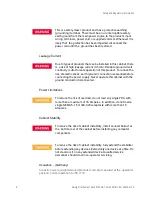
Page 7: ...or familiarization with safety markings and instructions before operation Safety Warnings The following warnings and cautions are applicable to all Keysight racks Please observe all safety precautions and warnings Grounding This product has not been evaluated for connection to an IT power system an AC distribution system having no direct connection to earth ground according to EN60950 The WARNING ...

Page 8: ...in this cabinet there is a risk of high leakage current 3 5 mA Reliable ground circuit continuity is vital for safe operation of this product To reduce the risk of electric shock earth ground connection is essential before connecting the power supply Never operate this cabinet with the ground conductor disconnected To reduce the risk of overload do not load any single PDU with more than a maximum ...

Page 9: ...d Use of Equipment The Keysight E7590A E3661B and E3662B Instrument Racks are intended to be used along with the recommended accessories for the installation of standard 19 inch rack mounted instruments from Keysight and other manufacturers Cleaning Disconnect the power from the instrument rack before cleaning the instrument rack and accessories Use only a damp cloth to clean the surfaces of the i...

Page 10: ...hown in the table below depend on the power distribution unit PDU option selected Option AW1 No PDU Option AW3 100 120V 50 60 Hz PDU Option AW5 200 240V 50 60 Hz PDU Model Number E3661B AW1 E3662B AW1 E7590A AW1 E7590A AW3 E7590A AW5 E3661B AW3 E3662B AW3 E3661B AW5 E3662B AW5 Input 100 120V 50 60 Hz 200 240V 50 60 Hz 100 120V 50 60 Hz 200 240V 50 60 Hz Output 100 120V 50 60 Hz 16A 1 IEC 320 C13 R...

Page 11: ...minated with a NEMA 5 20P plug to fit a 20A receptacle 200 240V 50 60 Hz racks Option AW5 are supplied without a power plug the PDU power cord is un terminated The installer must install the correct plug for the country of installation All racks Option AW3 or AW5 must be connected to a dedicated 20A circuit Rack Height Width Depth Weight E7590A 1 3 m 51 9 in 6 m 23 6 in 905 m 35 6 in 140 6 kg 310 ...

Page 12: ...2B 2 0 Description Dimensions The side view in Figure 2 shows valid dimensions for the E7590A E3661B and E3662B Figure 2 Side View of Top of Rack with Installed Components The dimensions of the E7590A are shown in Figures 3 All dimensions are in millimeters ...

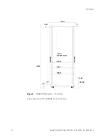
Page 13: ...Keysight Instrument Rack E7950A 1 3m E3661B 1 6m E3662B 2 0 13 Figure 3 E7590A Dimensions Front View The dimensions of the E3661B are shown below ...

Page 14: ...14 Keysight Instrument Rack E7950A 1 3m E3661B 1 6m E3662B 2 0 Description Figure 4 E3661B Dimensions Front View The dimensions of the E3662B are shown below ...

Page 15: ...lation and Heat Dissipation Air is primarily drawn through the opening at the bottom of the rear door Through convection the heated air rises to the exhaust By either simple convection or a combination with an optional extractor fan the heated air exhausts though the vented top cap illustrated in Figure 6 ...

Page 16: ...ng parts are included with every Keysight instrument rack Top The top of the rack incorporates a ventilation path through the roof of the rack and the convection current heat exit for the heat generated by the installed equipment Side Panels Lift up and off side panels allow fast and easy access from either side for installation servicing and removal of equipment The top cap need not be removed to...

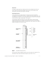
Page 17: ... holes for securing the rails The hole placement is chosen to conveniently place EIA racks Every fifth rectangular hole is slotted to make counting easier See Figure 7 The mounting columns bolt into the corners of the frame and then accept supporting rails into pre configured mounting slots Each of two rails attaches between the front and rear columns The equipment is then mounted on a pair of sup...

Page 18: ...rail Only after securing a pair of rails with screws can equipment be installed The mounting slots in the columns are positioned to make support rail placement convenient in EIA units Additionally they are marked to make matching the heights of matching support rails easy Figure 8 System II Rail with Support Columns and Attaching Hardware Rack Lifting Hooks Four lifting hooks are fitted to the top...

Page 19: ...20V option AW5 PDU can be ordered with each rack A maximum of two PDUs can be installed in one rack PDU Install Kit A PDU installation kit is installed at the factory for the above PDU each installation kit has the capability for installation of a second PDU A second PDU can be ordered and installed by the customer Extractor Fan An extractor fan assembly can be ordered and consists of two 100 cubi...

Page 20: ...d for use with the rack with EIA IEC mounting holes and attaching hardware They can be ordered in 7 different sizes measured in EIA units mm or in Ballast Ballast is available in 30 lb kits and may be required when using slide mounted products and or keyboard work surface products Use the stability work sheets in the Procedures chapter to determine ballast requirements Monitor Mount Kit An optiona...

Page 21: ...3661B 1 6m E3662B 2 0 21 Non Keysight Rail Non Keysight rails are used with any non Keysight products that mount at the bottom of the EIA envelope The Non Keysight rails extend lower into the EIA envelope than the standard and the VXI rails ...

Page 22: ...ed The rack requires a minimum of 600 mm for rear door clearance Equipment Installation Guidelines Several guidelines should be kept in mind when installing equipment into racks The two main considerations are weight and balance for slide mounted equipment and heat dissipation This section includes some worksheets for calculating the weight and balance for slide mounted products and an optional wo...

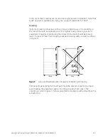
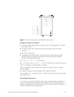
Page 23: ...ack and placement of the highest heat producing pieces of equipment Equipment protruding the closest to the back should be placed lower to prevent them from trapping heat and creating eddy currents as shown in Figure 9 Figure 9 Good and Bad Examples of Equipment Racking Vs Cooling Components generating the most heat should be placed closest to the top to avoid heating the equipment above it as the...

Page 24: ...alculate both and add the results Slide Mounted Products To reduce the risk of rack instability when operator serviceable slide mounted products are installed use the following worksheet to determine the need for additional counterweight ballast If there are no operator serviceable slide mounted products in the rack this worksheet can be ignored An operator serviceable slide mounted product is def...

Page 25: ...M2 totals from above M1 A B C D 1 25 ft ft lbs M2 16 1 ft lbs a b c d 1 00 ft ft lbs If M1 is less than or equal to M2 no additional counter weight is needed If M1 is greater than M2 use the formulas below to determine the required counter weight 4 Determine required counter weight if M1 is greater than M2 Force in lbs M1 M2 ft lbs 2 05 ft amount of force 2 05 ft Each ballast kit weighs 30 lbs Wor...

Page 26: ...he M1 and the fixed and trained service personnel serviceable slide mounted products M2 totals from above M1 180 lbs D ft _ft lbs moment of rack with 180 lbs of force applied at D feet M2 254 00 ft lbs a b c d 1 00 ft ft lbs If M1 is less than or equal to M2 no additional counter weight is needed If M1 is greater than M2 use the formulas below to determine the required counter weight 4 Determine r...

Page 27: ...active interference is present Total system noise is impossible to calculate completely accurately Therefore system acoustic performance should be measured to ensure that acoustic goals are met However assuming the worst case constructive noise levels some general estimating guidelines can be used to combine noise levels of system products used together Acoustic sound power and pressure data are l...

Page 28: ...nits 10x 10 100 5 Take the log of both sides of the equation return to dB units x 10 dB log 0 5 6 837 dB Solve for x x 68 37 dB More than double the noise is required to increase the total noise from 65 dB to 70 dB Estimating Total Noise For a quick estimate of total noise from two sources see Figure 13 if the two dB levels are within 16 dB of each other If the difference is greater than 16 dB the...

Page 29: ...ed Inspect the rack for damage scratches dents bent pieces etc If the rack is damaged notify the carrier and the nearest Keysight Technologies Sales and Service office immediately Unpacking and Handling The lifting brackets supplied with the rack are suitable for lifting the rack when fully loaded Use the following procedure to remove the rack from the shipping base One person can perform this pro...

Page 30: ...ap from the shipping box 3 Remove the corrugated wrap from the pallet 4 Remove the packing materials Figure 14 Lifting the Packing Lid Off 5 Remove the folded ramp from the side of the rack 6 Remove the two bolts 1 holding the anti roll block in place at the bottom rear see Figures 15 Remove the block ...

Page 31: ...pping clamp at the bottom of the frame They are bolted to the pallet 8 Remove the clamp 3 9 Unfold and position the ramp so that the block of wood under the ramp locks into the edge of the pallet with the strip of wood forming a lip This holds the ramp in place while the rack is moved across the pallet and down the ramp See Figure 16 ...

Page 32: ...shipment securely place a tag on the container and equipment to identify the owner and the service to be performed Include the rack model number To repackage the rack follow the repackage checklist below and refer to the unpacking instructions for details 1 Assemble the original Keysight packing materials 2 Connect the loading ramp to the pallet Make sure that the leveling feet on the rack are rai...

Page 33: ...or the standard assembly Rear Door Removal 1 Open rear door 2 Disconnect the bonding wire from the door 3 Grasp the rear door support and lift the door straight up and away from the cabinet Rear Door Replacement 1 Hold the rear door by the support column 2 Align the door hinge pins over the rack hinge holes 3 Lower the door onto the rack hinge 4 Reconnect the door onto the rack hinge Top Cap Remov...

Page 34: ...s at the bottom of the rack 4 On the right side cover insert and tighten the two mounting screws on the upper door hinge that secure the hinge to the side panel Forehead Assembly Removal 1 Turn the power OFF Disconnect AC power to the rack 2 Remove top cap assembly refer to top cap removal 3 Unplug the PDU harness es from the back of the main power switch if present 4 Remove the three mounting scr...

Page 35: ...t stops 2 Lift the two sidebars that go into the rack frame and pull the stabilizer away from the rack Anti tip Stabilizer Replacement 1 Align the two extension arms with the opening at the bottom of the rack and insert the arms at an angle This allows the stop tabs to go into the rack cavity for the stabilizer 2 Push the anti tip stabilizer all the way into the rack Rear Door Hinge Removal 1 Remo...

Page 36: ...ide the clamp out of the rail groove Rail Replacement 1 Slide the rail clamp onto the rail 2 Insert the rail tabs into the appropriate support column notches 3 Insert and tighten the two mounting screws through the rail into the clip nuts on the column 4 Reinstall the component 5 Slide the rail clamp up to the rear of the component and insert the clamp screw Leveler or Caster Removal 1 Turn the ra...

Page 37: ...ews Ballast should be installed at the bottom of the rack resting adjacent to the rear base If ballast cannot be installed at the base of the rack it can be installed using the rack shelf Install additional ballast adjacent to each other so that they provide support for each other Door Bumper The rear and front door bumpers are self adhesive rubber bumpers stuck to the door Remove by prying off wi...

Page 38: ...This information is subject to change without notice Keysight Technologies 2015 Edition 3 August 2015 Published in USA 5967 9318 www keysight com ...

Reviews: