background image

XG12 Chassis installation precautions

The following precautions should be followed while installing the XG12 chassis:

l

The chassis should be installed in the rack before installing the power supply module, fan module
and load modules, thereby reducing the weight of the chassis.

l

The two lower bolts used to secure the chassis to a rack can be used to hold the chassis frame in
place while securing all of the other bolts.

l

Secure the chassis to rack face with all six bolts.

l

Fully depress power supply clamps when installing power supply module.

l

Secure the power supply module thumb bolt when installing power supply module.

l

Install the rear power supply cover before applying AC power. After removing or installing this
cover, ensure that the thumbscrews are tightened down with a 'Flat Blade' screwdriver.

l

Do not use the chassis without installing the Fan module.

l

Do not use the chassis without installing the Processor module.

l

Do not leave unused slots open. Use the filler panels to cover the un-used slots.

l

Do not block the front air intake.

l

A minimum air flow clearance of 12 inches is required. 24 inches of air flow clearance is preferred
at the rear of the chassis.

l

Operator intervention may be required to power cycle the XG12 chassis or restart a software
program in the event the XG12 chassis operation is upset or stopped by electrostatic discharge.

Chapter 3  Install XG12 Chassis

– 6 –

Summary of Contents for Ixia XG12

Page 1: ...XG12 Chassis Release 9 10 Assembly Guide Document version 202008071846 05 30...

Page 2: ...y provided to the public Accordingly Keysight provides the Software to U S government customers under its standard commercial license which is embodied in its End User License Agreement EULA a copy of...

Page 3: ...notice denotes a hazardous situation that if not avoided could result in minor or moderate injury A WARNING notice denotes a hazardous situation that if not avoided could result in death or serious i...

Page 4: ...0 4939 6410 support ixiacom com Australia 61 742434942 support ixiacom com EMEA Support 40 21 301 5699 support emea ixiacom com Greater China Region 400 898 0598 support china ixiacom com Hong Kong 85...

Page 5: ...This page intentionally left blank v...

Page 6: ...er 3 Install XG12 Chassis 5 XG12 Chassis installation precautions 6 Un pack and mount the chassis 7 Remove and insert processor module 8 Remove and insert power supply module 9 Power cords 11 Remove a...

Page 7: ...This page intentionally left blank vii...

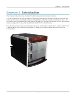
Page 8: ...s of the Xcellon Flex load modules It is a 12 slot chassis with increased total power capacity available for all load modules and front to back airflow delivery along with increased bandwidth from the...

Page 9: ...This page intentionally left blank 2...

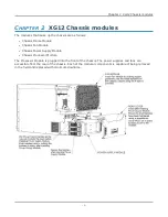
Page 10: ...Chassis Power Supply Module l Chassis Processor Module The Processor Module is plugged into the front of the chassis The power supplies and fans are accessible from the rear of the chassis Each of the...

Page 11: ...This page intentionally left blank 4...

Page 12: ...is documentation and provides a list of related documentation Section contents XG12 Chassis installation precautions 6 Un pack and mount the chassis 7 Remove and insert processor module 8 Remove and i...

Page 13: ...alling power supply module l Install the rear power supply cover before applying AC power After removing or installing this cover ensure that the thumbscrews are tightened down with a Flat Blade screw...

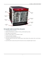
Page 14: ...arton 4 Remove power supply cover and keep it aside 5 Remove the plastic wrapping 6 Insert the lowermost screws on the rack 7 Slide the chassis into the rack so that the lower screw notches of the cha...

Page 15: ...air baffles 48 lbs l 3 power cords 6 lbs l Power supply assembly 29 lbs l Fan Assembly 10 lbs l CPU card 4 lbs Do not attempt to lift the fully assembled chassis Remove and insert processor module To...

Page 16: ...h them in 3 Fasten the screws Remove and insert power supply module The power supply module is accessible after removing the rear cover To remove the rear cover unfasten the four screws around the cov...

Page 17: ...ve the individual power supplies 1 Hold the handle on the power supply 2 Pull the clip inwards and then pull the handle out To insert the individual power supplies slide the power supply in until you...

Page 18: ...module 5 Replace the rear cover and fasten it with the screws Power cords The XG12 chassis is CE marked and UL certified when using the 200 240VAC power cords supplied with the chassis However these c...

Page 19: ...fan module is located on the rear side of the chassis To remove the fan module 1 Unfasten the four screws that are present on the edges of the fan module 2 Pull the module outwards To install the fan...

Page 20: ...he password is the CPU module serial number found on the sticker located in front of the CPU module The two network ports on the CPU module are configured by default for DHCP Note The chassis windows...

Page 21: ...This page intentionally left blank 14...

Page 22: ...9 inserting processor module 8 Installing chassis 5 L logging on 13 M modules 3 mounting the chassis 7 O Overview 1 P Power cords 11 precautions 6 R Removing fan module 12 removing power supply module...

Page 23: ...Ixia a Keysight Business 26601 West Agoura Road Calabasas California 91302 Keysight Technologies 2020...

Reviews: