background image

Keysight W6600A-series LPDDR4 BGA Interposers Installation Guide

69

Making Power Integrity Measurements using W6600A-series Interposers

8

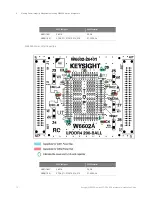
W6600A-Series Interposers Power Filter Capacitors

The interposers in the W6600A-series have locations for VDD and VDDQ bypass capacitors. The 

following diagrams highlight these locations. 

W6601A Power Filter Capacitors

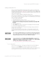
CAUTION

While making power integrity probing connections, you must observe polarity for power filter 

capacitors as indicated using the green ellipses in the diagrams below 

Summary of Contents for LPDDR4

Page 1: ...Keysight W6600A Series LPDDR4 BGA Interposers Installation Guide ...

Page 2: ... the Software to U S gov ernment customers under its standard com mercial license which is embodied in its End User License Agreement EULA a copy of which can be found at http www key sight com find sweula The license set forth in the EULA represents the exclusive authority by which the U S government may use modify distribute or disclose the Soft ware The EULA and the license set forth therein do...

Page 3: ... left wing probe cable 160 pin direct connect to LA This probe cable is for use with the W6601A interposer U4209A 61 pin ZIF from right wing probe cable 160 pin direct connect to LA This probe cable is for use with the W6601A interposer W6602A LPDDR4 RC BGA Interposer 200 ball rigid U4207A Zero ohm 34 channels Soft Touch Pro single ended probe cable 160 pin direct connect to LA This probe cable is...

Page 4: ...4 Keysight W6600A series LPDDR4 BGA Interposers Installation Guide ...

Page 5: ...nd Software Requirements 16 Mechanical Considerations 18 W6601A Interposer Dimensions 18 W6601A Riser Dimensions 19 W6601A Keep Out Volume 19 3 Introduction to W6602A LPDDR4 BGA Interposer W6602A LPDDR4 RC BGA Interposer 200 ball Rigid 22 Software Configurations 23 W6602A Technical Features Summary 24 W6602A Riser 24 U4207A Zero ohm 34 channels Soft Touch Pro Single ended Probe Cable 25 Hardware a...

Page 6: ...2A Clock Connectors 50 U4207A Flying Leads Orientation 51 Step 3 Connecting the W6602A Interposer to U4207A Probes 53 Step 4 Connecting the U4207A Probe Pods to the Logic Analyzer Module Pods 54 For Two 16 bit Channels DRAM Configuration 54 For a Single 32 bit Channel DRAM Configuration 56 W6602A Interposer Footprints Pinout 58 W6602A Clock Connectors Pinout 59 W6602A Clock Qualifier and RESET Con...

Page 7: ...rrelating Power Integrity Measurements with Memory Analysis Measurements 71 9 Characteristics Regulatory Safety and Storage Information Operating Characteristics 74 Storage Inspection Baking and Cleaning Guidelines 75 Guidelines for Shelf Life and Solder ability of W6600A series Interposers 75 Cleaning of W6601A Interposer Gold Fingers 75 Regulatory Notices 76 WEEE Compliance 76 China RoHS 76 Inde...

Page 8: ...8 Keysight W6600A series LPDDR4 BGA Interposers Installation Guide Contents ...

Page 9: ...n the common footprint passes directly from the bottom side of the interposer to the top side of the interposer Currently in this series Keysight provides the following interposers All probing including BGA interposers become a part of the system under test when installed Maximum data rates and performance results will vary by systems under test BGA rework and probing irregularities Compatibility ...

Page 10: ...1 Introduction 10 Keysight W6600A series LPDDR4 BGA Interposers Installation Guide ...

Page 11: ... pin ZIF Probe Cable for Right Wing 15 Hardware and Software Requirements 16 Mechanical Considerations 18 This chapter introduces the hardware components that are needed for the W6601A LPDDR4 BGA interposer setup It also lists the software requirements as well as describes the mechanical considerations such as various dimensions and KOV that you should know before you start setting up and using th...

Page 12: ...The interposer probes a subset of the DQ data lines of both banks of such an LPDDR4 BGA 200 DRAM This interposer is optimized to work with the U4164A logic Analyzer module to achieve higher data rates with smaller KOV Software Configurations The W6601A interposer can be used in the following three logic analyzer software configurations 10 GHz Timing mode State mode under 2500 Mb s double edge cloc...

Page 13: ...nts network is present on the W6601A interposer No RC network present on the U4208A U4209A probe cables Also there are no RCs on the bottom of the interposer Has a power plane and separate ground planes 1 1 V VDD2 VDDQ and 1 8 V VDD1 Also provides VDD and VDDQ power filter capacitors to allow you to make power integrity measurements using the Keysight Power Rail probe and Infiniium S series oscill...

Page 14: ...1A interposer to a U4208A probe cable refer to the following topics in this guide Step 2 Connecting the W6601A Interposer to U4208A and U4209A Probe Cables on page 40 To get information such as its characteristics specifications pinout safety information accessories and dimensions of the U4208A probe cable refer to the Keysight U4200A Series Probes and Cables User Guide part number U4200 97000 ava...

Page 15: ...nnect a W6601A interposer with a U4209A probe cable refer to the topic Step 2 Connecting the W6601A Interposer to U4208A and U4209A Probe Cables on page 40 To get information such as its characteristics specifications pinout safety information accessories and dimensions of the U4209A probe cable refer to the Keysight U4200A Series Probes and Cables User Guide part number U4200 97000 available on w...

Page 16: ...quired for W6601A Default LPDDR configuration files Required Available as an unlicensed standard feature with the B4661A package Includes default XML configuration files for use with the W6601A interposer DDR Setup Assistant and DDR Eyefinder software version 6 30 or higher Required Available as an unlicensed standard feature with the B4661A package A wizard like application to help you set up you...

Page 17: ...re components by downloading the required executables from the Keysight web site at www keysight com find lpa sw download DRAM Data Width Access to Number of Interposers Number of ZIF Probes Number of Logic Analyzer Modules LPDDR4 200 ball DRAM used as a single 32 bit channel device Dual bank 16 bit Ck_A All Channel A CA and control signals for Bank 0 and Bank 1 All DBI signals Subset of DQS and D...

Page 18: ...8 Keysight W6600A series LPDDR4 BGA Interposers Installation Guide Mechanical Considerations W6601A Interposer Dimensions The following figure shows the dimensions of a W6601A LPDDR4 BGA interposer Figure 5 Dimensions of a W6601A interposer Top View ...

Page 19: ...9 Introduction to W6601A LPDDR4 BGA Interposer 2 W6601A Riser Dimensions All dimensions are in inches W6601A Keep Out Volume NOTE You must install the W6601A interposer on a riser shipped with the interposer or a grypper socket to provide clearance to surrounding DRAM ...

Page 20: ...2 Introduction to W6601A LPDDR4 BGA Interposer 20 Keysight W6600A series LPDDR4 BGA Interposers Installation Guide Figure 6 KOV of a W6601A interposer ...

Page 21: ...ro Single ended Probe Cable 25 Hardware and Software Requirements 26 Mechanical Considerations 28 This chapter introduces the hardware components that are needed for the W6602A LPDDR4 BGA interposer setup It also lists the software requirements as well as describes the mechanical considerations such as various dimensions that you should know before you start setting up and using the W6602A interpo...

Page 22: ...M used as two 16 bit channels An LPDDR4 DRAM used as a single 32 bit channel This interposer supports probing of all CA and DQ DQS signals for both channels of a 200 ball LPDDR4 DRAM high speed data capture data rates up to 3 2 Gb s lower system loading NOTE The W6602A interposer with the U4207A cable passively monitors the LPDDR4 200 ball DRAM package After tuning the Keysight logic analyzer Comm...

Page 23: ... clocking CHB State mode 16 DQ under 2500MT s double edge clocking CHB State mode 16 DQ over 2500MT s single edge clocking This interposer effectively utilizes the single touch probing and quad sampling features of the U4164A logic analyzer module thereby allowing you to probe LPDDR4 DQ signals above 2 5Gb s without double probe load In quad sampling four samples are captured per clock edge at two...

Page 24: ... VDDQ power filter capacitors to allow you to make power integrity measurements using the Keysight Power Rail probe and Infiniium S series oscilloscope W6602A Riser An LPDDR4 BGA 200 ball riser is provided with each W6602A interposer to allow the interposer to clear surrounding devices Optionally you can use a Grypper socket It is not provided with the interposer The following figure displays a ri...

Page 25: ...obe cable refer to the following topics in this guide Step 3 Connecting the W6602A Interposer to U4207A Probes on page 53 To get information such as its characteristics specifications pinout safety information accessories and dimensions of the U4207A probe cable refer to the Keysight U4200A Series Probes and Cables User Guide part number U4200 97000 available on www keysight com Soft Touch Pro Con...

Page 26: ...d software features from the B4661A software package are required for W6602A Default LPDDR configuration files Required Available as an unlicensed standard feature with the B4661A package Includes default XML configuration files for use with the W6601A interposer DDR Setup Assistant and DDR Eyefinder software version 6 40 or higher Required Available as an unlicensed standard feature with the B466...

Page 27: ...w download DRAM Data Width Access to Number of Interposers Number of U4207A Probes Number of Logic Analyzer Modules LPDDR4200 ball DRAM Two 16 bit channels or Single32 bit channel All CA and DQ signals for both channels A and B One W6602A Two U4207A probes for each W6602A interposer For a single 32 bit channel DRAM configuration Two U4164A modules combined via cables to form a module set represent...

Page 28: ...ht W6600A series LPDDR4 BGA Interposers Installation Guide Mechanical Considerations W6602A Interposer Dimensions The following figure shows the dimensions of a W6602A LPDDR4 BGA interposer Figure 10 Dimensions of a W6602A interposer Top View 0 067 thickness ...

Page 29: ...Keysight W6600A series LPDDR4 BGA Interposers Installation Guide 29 Introduction to W6602A LPDDR4 BGA Interposer 3 W6602A Riser Dimensions ...

Page 30: ...3 Introduction to W6602A LPDDR4 BGA Interposer 30 Keysight W6600A series LPDDR4 BGA Interposers Installation Guide ...

Page 31: ...hat interposers be installed by companies with specific expertise in this advanced type of processing Keysight does not endorse any specific BGA rework facility but recommends using a reputable and experienced BGA rework facility for the installation of BGA interposers The following links are provided as a convenience to users investigating BGA rework facilities Information on BGA Rework Facilitie...

Page 32: ...des 9 1 1 shtml BGA Component Rework Inspection http www circuitrework com guides 9 1 2 shtml BGA Component Rework Profile Development Standard Method http www circuitrework com guides 9 2 1 shtml BGA Component Rework Profile Development Smart Track Method http www circuitrework com guides 9 2 2 shtml BGA Component Rework Eutectic Solder Ball http www circuitrework com guides 9 3 1 shtml BGA Compo...

Page 33: ...ologies The maximum processing temperature that the W6600A series interposers can withstand is 260 C for not more than 90 seconds The W6600A series interposers are supplied without solder balls Depending on the exact attachment order either leaded or lead free solder may be preferred to attach the interposer to the DUT The design of the interposer supports either choice Applicable only to the wing...

Page 34: ...ithin a few hours these should be re baked or placed in a desiccant chamber 3 Heat Shielding applicable only to winged interposers in this series such as the W6601A interposer a Kapton tape is applied to the bottom side covering the gold contact area and wrapping around the outside edge to the top side b Three layers of Kapton tape are applied to the top side covering the entire wing extending ove...

Page 35: ...com NA UT HNAUTTDS nsf web 7DA17BAB270FA76E882571870000D 6EE File 3609 EN pdf b Apply solder paste to the top side of interposer c Position memory using an SRT or equivalent with vision system for manual placement d Reflow per the prepared heating profile 8 Post Processing a Remove flux residue b Remove any Kapton tape heat shielding and peelable mask material c Remove heat shielding from the targ...

Page 36: ...perating in a soldered down environment over a wide range of temperatures the expansion coefficient of the interposer DRAM and system being probed must be matched to avoid stress related failure of the solder connections between the Interposer and attached components The interposer material allows operation over an industrial temperature range of 40 to 85 degrees Celsius non condensing subject to ...

Page 37: ...etting up the W6601A Inter poser W6601A Interposer Setup Overview 38 Step 1 Soldering the W6601A Interposer 39 Step 2 Connecting the W6601A Interposer to U4208A and U4209A Probe Cables 40 Step 3 Connecting the U4208A and U4209A Probe Cables to a U4164A Logic Analyzer 43 ...

Page 38: ...obe cables See page 40 3 Connect the U4208A and U4209A probe cables to a U4164A Logic Analyzer module s pods See page 43 CAUTION Use ESD precautions Electrostatic discharge can damage components on your board or in the interposer Use a grounded wrist strap and other ESD control measures as appropriate NOTE Do not open the vacuum sealed packs of the W6601A interposer until you are ready to install ...

Page 39: ...ser assembly to the DUT The interposer is designed to tolerate lead free soldering temperature profiles However it is always recommended to apply the minimum temperature required and the minimum number of heating cooling cycles to reduce risk of any damage to the interposer The stack up of these soldered components is illustrated in the following figure Figure 11 PC board riser interposer and DRAM...

Page 40: ...nt to label pods as follows As illustrated in the diagram below you need to connect the U4208A probe cable to the left wing of the interposer the U4209A probe cable to the right wing of the interposer Figure 12 W6601A Interposer and U4208A U4209A Probe Cable Connections The door on the ZIF connector of the U4208A U4209A cable closes against the top of the ZIF wing of the interposer CAUTION Please ...

Page 41: ...poser s wing notches 3 Shut the ZIF door W6601A Interposer Wings Pinout The table on the next page lists the pinout of the two wings of a W6601A interposer The table includes the signals being probed when using the interposer in a dual sampling mode or a quad sampling mode supported by the U4164A logic analyzer module In this table Clock Qualifier inputs are highlighted with yellow Signals that ca...

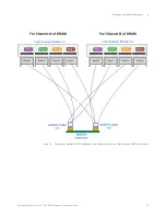
Page 42: ... Right Wing Left Wing 2 DQ8_A DQ0_B 4 DQ9_A 6 DMI1_A DQ7_B 8 DQ15_A 10 CKc_A 12 CKt_A 14 CA2_A DMI0_B 16 CA3_A 18 CA4_A DQ1_B 20 CA5_A 22 DQ2_B 24 26 DQ4_B 28 DQ12_B 30 GND CKE1_A 32 RESET_N GND 34 DQ3_B 36 DQ11_B 38 CS1_A 40 DQ10_B 42 CS0_A 44 DQ9_B CA1_A 46 CA0_A 48 DMI1_B ODT_CA_A 50 CKE0_A 52 GND 54 DQ7_A 56 DQ15_B DMI0_A 58 DQS0t_A 60 DQ8_B DQ0_A Pin U4209A U4208A ...

Page 43: ...a U4164A Logic Analyzer as per the connection diagram in Figure 13 the logic analyzer channels are mapped to DDR4 signals as per the table displayed below These signals are automatically configured when you load one of the configuration files supplied with the Keysight B4661A LPDDR decoder software Probe Cable Pods U4164A Logic Analyzer Pods U4209A Cable Pods Pod A Pod 7 Pod B Pod 1 U4208A Cable P...

Page 44: ...cessible Table 2 Signals and Logic Analyzer Channels Mapping when using the W6601A Interposer Logic Analyzer Pod and its Channels Signals on U4208A probe cable Pod A Logic Analyzer Pod and its Channels Signals on U4208A probe cable Pod B Pod 3 0 DQ0_B Pod 5 0 CS0_A 1 1 2 DQ7_B 2 CA1_A 3 3 4 DMI0_B 4 CA0_A 5 5 6 DQ1_B 6 ODT_CA_A 7 7 8 DQ2_B 8 DQ7_A 9 9 10 DQ4_B 10 DMI0_A 11 11 12 DQ3_B 12 DQS0t_A 1...

Page 45: ...onnections for the W6601A interposer Logic Analyzer Pod and its Channels Signals on U4209A probe cable Pod A Logic Analyzer Pod and its Channels Signals on U4209A probe cable Pod B Pod 7 0 DQ8_B Pod 1 0 CA5_A 1 1 2 DQ15_B 2 CA4_A 3 3 4 DMI1_B 4 CA3_A 5 5 6 DQ9_B 6 CA2_A 7 7 8 DQ10_B 8 DQ15_A 9 9 10 DQ11_B 10 DMI1_A 11 11 12 DQ12_B 12 DQ9_A 13 13 14 14 DQ8_A 15 15 CLK RESET_N CLK CKt_A CLK GND CLK ...

Page 46: ...oser Signal Name W6601A DNU VDDQ VDD1 VDD2 ODT_CA_B CA0_B CA1_B DQ3_A DQ2_A DQ1_A DQS0c_A CS1_B DQS0c_B DQS0t_B DQ6_B DQ5_B CS0_B CKE0_B DQ4_A DQ5_A DQ6_A ZQ0 CS2_B CKE1_B ZQ1 CKE2_A CKE2_B CKt_B DQ14_B DQ13_b CA2_B CKc_B DQ12_A DQ13_A DQ14_A DQS1t_A DQS1c_A CA3_B DQS1c_B DQS1t_B CA4_B CA5_B ZQ2 DQ11_A DQ10_A ...

Page 47: ...ep 1 Soldering the W6602A Interposer 49 Step 2 Making Clock Qualifier Connections 50 Step 3 Connecting the W6602A Interposer to U4207A Probes 53 Step 4 Connecting the U4207A Probe Pods to the Logic Analyzer Module Pods 54 W6602A Interposer Footprints Pinout 58 W6602A Clock Connectors Pinout 59 Logic Analyzer Channels to Signals Mapping 61 ...

Page 48: ...er the retention modules to the connectorless footprints on top of the W6602A Attach the U4207A probes to these retention modules See page 53 Step 4 Connect the U4207A probe cables to the Logic Analyzer module pods See page 54 CAUTION Use ESD precautions Electrostatic discharge can damage components on your board or in the interposer Use a grounded wrist strap and other ESD control measures as app...

Page 49: ... temperature profiles However it is always recommended to apply the minimum temperature required and the minimum number of heating cooling cycles to reduce risk of any damage to the interposer The stack up of these soldered components is illustrated in the following figure Figure 14 PC board riser interposer and DRAM stack up Refer to the chapter W6600A Series Interposers and Riser Soldering Guide...

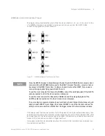
Page 50: ...ins represents Figure 15 W6602A clock connectors and pins for these connectors To make clock qualifier connections you use the Single Pin Headers part number W6602 60001 included in the W6602A shipment Figure 16 Single Pin Header 1 Solder the single pin headers into the clock connectors of the interposer from the top of the interposer Following are some of the recommendations for this soldering st...

Page 51: ...stallation Guide 51 Setting up the W6602A Interposer 6 2 Attach the clock qualifier connection flying leads of U4207A to the soldered single pin headers U4207A Flying Leads Orientation A clock qualifier connection flying lead of U4207A has two wires ...

Page 52: ...quare pin of the clock connector and the gray wire with the signal pin round pin of the clock connector When you solder the single pin headers into the clock connectors the shapes of the GND pins and signal pins get hidden beneath the soldered single pin headers In such a situation you can ensure the correct orientation of the flying leads by identifying the signal pin as the pin which is the clos...

Page 53: ... number E5403A Figure 17 W6602A Interposer connected to a U4207A Probe 1 Attach the retention module to the interposer from the top a Insert the retention module into the interposer noting the keying pin b Solder alignment pins from the top ensuring that solder is added until a fillet is visible on the pin 2 Insert the U4207A probe into the retention module a Ensure proper keying by aligning the K...

Page 54: ...n pods of the logic analyzer modules are NOT used This mapping of the cable pods and logic analyzer pods is also illustrated with the help of the following diagram NOTE For this type of DRAM configuration setup you need to use the two U4164A modules as independent modules one for each 16 bit channel This allows you to have separate master clocks for probing the DRAM s channel A and B by using mast...

Page 55: ...ht W6600A series LPDDR4 BGA Interposers Installation Guide 55 Setting up the W6602A Interposer 6 Figure 18 Connections between U4207A cables and Logic Analyzer pods for two 16 bit channels DRAM configuration ...

Page 56: ...tion guide of your logic analyzer module to know how to create a modules set This guide is available on the module s page on www keysight com In this modules set the bottom module acts as the clocking module providing the master clock for the 32 bit single channel setup For a Single 32 bit Channels Configuration U4207A Cable Pods U4164A Logic Analyzer Bottom Module Pods This is the master module i...

Page 57: ...6 Figure 19 Connections between U4207A cables and Logic Analyzer pods for a single 32 bit channel DRAM configuration NOTE In the 32 bit single channel setup the W6602A interposer probes and uses only one set of CA signals as this configuration implies that the two CA channels on the DRAM are identical ...

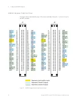
Page 58: ...ies LPDDR4 BGA Interposers Installation Guide W6602A Interposer Footprints Pinout The diagram below illustrates the pinout of the two connectorless footprints J1 and J2 on top of a W6602A interposer Figure 20 W6602A Interposer Connectorless Footprints Pinout ...

Page 59: ...k qualifier inputs on the master U4164A module in any module set can be used as clock qualifiers NOTE Since the RESET_N signal is shared between Channel A and B of DRAM there is only one clock connector J6 on the W6602A interposer for the RESET_N signal Therefore only one channel has access to the RESET_N at a time To allow a channel to access the RESET_N you need to connect the appropriate flying...

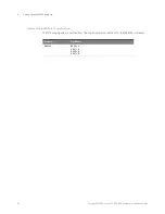
Page 60: ...02A In the Channel A 16 bits software configuration this signal is named CKE1 Use the purple flying lead of the U4207A cable that you connected to J1 on the W6602A interposer Connect this purple flying lead to either CKE1_B or CKE2_B pin header J4 or J7 connector of W6602A In the Channel B 16 bits software configuration this signal is named CKE1 Use the orange flying lead of the U4207A cable that ...

Page 61: ...the U4207A clock connection flying leads For Channel A Logic Analyzer 1 Pod Signals on Pod Logic Analyzer 1 Pod Signals on Pod Logic Analyzer 1 Pod Signals on Pod Logic Analyzer 1 Pod Signals on Pod Pod 1 CA5_A Pod 3 DQ2_A Pod 5 DQ7_A Pod 7 DQ8_A CA2_A DQ3_A DQ6_A DMI1_A CA4_A ODT_CA_A DQ4_A DQS1_t_A DQ12_A CS1_A DQ5_A DQ13_A CA3_A CS0_A DQS0_t_A DQ14_A DQ11_A CA0_A DMI0_A DQ15_A DQ10_A CS2_A DQ0_...

Page 62: ...A series LPDDR4 BGA Interposers Installation Guide Signals not probed by the Logic Analyzer The following signals are omitted from the Logic Analyzer connections for the W6602A interposer Interposer Signal Name W6602A DQS0_c_A DQS1_c_A DQS0_c_B DQS1_c_B ...

Page 63: ...PDDR4 BGA Interposers Installation Guide 7 Setting Up the Logic Analyzer for W6600A series Interpos ers Before You Start 64 Loading a Configuration File 65 Troubleshooting Problems with Thresholds and Sample Positions Setup 66 ...

Page 64: ...terposers Installation Guide Before You Start Ensure that all the software components listed in the topic Hardware and Software Requirements on page 16 and Hardware and Software Requirements on page 26 are installed on the host computer and the required software licenses are also obtained and installed ...

Page 65: ...the BGA and then choose a configuration file corresponding to the bus size and speed 5 Double click the configuration file to open it When you click on a configuration file the Logic and Protocol Analyzer software will start and configure itself to use the decoder The logic analyzer Buses Signals setup dialog allows you to assign descriptive labels to each analyzer channel that associate each chan...

Page 66: ...blems such as clock edges that are too close together or eyes that are closing in the LPDDR eyescans that you generated in the Logic and Protocol Analyzer GUI please refer to the following topic in the DDR Setup Assistant software user guide online help Solving Problems with Thresholds and Sample Positions Set Up You can find the DDR Setup Assistant user guide by searching for DDR Setup Assistant ...

Page 67: ...rposers Installation Guide 8 Making Power Integrity Measurements using W6600A Series Interposers Overview 68 W6600A Series Interposers Power Filter Capacitors 69 Correlating Power Integrity Measurements with Memory Analysis Measurements 71 ...

Page 68: ...measure periodic and random disturbances PARD static and dynamic load response programmable power rail response and similar power integrity measurements Power Integrity Measurement Setup To make power integrity measurements you need the following Keysight products W6600A series Interposer Infiniium S series DSO and MSO High definition Oscilloscope N7020A Power Rail Probe that connects to one of th...

Page 69: ...s Power Filter Capacitors The interposers in the W6600A series have locations for VDD and VDDQ bypass capacitors The following diagrams highlight these locations W6601A Power Filter Capacitors CAUTION While making power integrity probing connections you must observe polarity for power filter capacitors as indicated using the green ellipses in the diagrams below ...

Page 70: ...0A series LPDDR4 BGA Interposers Installation Guide W6602A Power Filter Capacitors 0201 Footprint 0402 Footprint VDD1 1 8 V C9 C10 C5 C6 VDDQ 1 2 V C7 C8 C11 C12 C13 C14 C15 C1 C2 C3 C4 0201 Footprint 0402 Footprint VDD1 1 8 V C9 C10 C5 C6 VDDQ 1 2 V C7 C8 C11 C12 C13 C14 C15 C1 C2 C3 C4 ...

Page 71: ...n to spikes on a power rail To create a setup for these correlated measurements you need the W6600A series interposer s setup with a U4164A interposer for the memory analysis measurements This setup is described in Chapter 6 Setting up the W6602A Interposer the W6600A series interposer s setup with an Infiniium S series oscilloscope for the power integrity measurements This is described in the pre...

Page 72: ...8 Making Power Integrity Measurements using W6600A series Interposers 72 Keysight W6600A series LPDDR4 BGA Interposers Installation Guide ...

Page 73: ...0A series LPDDR4 BGA Interposers Installation Guide 9 Characteristics Regulatory Safety and Storage Information Operating Characteristics 74 Storage Inspection Baking and Cleaning Guidelines 75 Regulatory Notices 76 ...

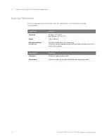
Page 74: ...stics Description Temperature Operating 5 C to 40 C Non Operating 40 C to 70 C Altitude 4 600 m 15 000 ft Relative Humidity Range Noncondensing 50 RH Min 80 RH Max at 40 C noncondensing Avoid sudden extreme temperature changes which could cause condensation on the circuit board For indoor use only Characteristics Description To interposer Memory bus signals from target system From interposer High ...

Page 75: ...proof vacuum sealed bag s If the humidity indicator shows moisture then bake the board at 120 degrees C for 4 hours and perform the solder ability test If the test passes proceed with the assembly reflow of interposer If delamination occurs the interposer cannot be used Cleaning of W6601A Interposer Gold Fingers Use Isopropyl alcohol to clean W6601A interposer contacts Never use abrasive cleaning ...

Page 76: ... 2002 96 EC marking requirements The affixed label indicates that you must not discard this electrical electronic product in domestic household waste Product Category With reference to the equipment types in the WEEE Directive Annex I this product is classed as a Monitoring and Control Instrumentation product Do not dispose in domestic household waste To return unwanted products contact your local...

Page 77: ...rposer 47 interposer inputs to 74 interposer outputs from 74 introduction 9 K KOV 19 L logic analysis system set up 63 logic analyzer channel mapping 43 61 logic analyzer connections 43 LPDDR configuration files 16 26 65 M mechanical considerations 18 28 O operating characteristics 74 P pinout 41 power filter capacitors 69 70 power integrity 68 probe to logic analyzer connections 54 R regulatory i...

Page 78: ...Index 78 Keysight W6600A series LPDDR4 BGA Interposers Installation Guide ...

Page 79: ...Keysight W6600A series LPDDR4 BGA Interposers Installation Guide 79 ...

Page 80: ...This information is subject to change without notice Keysight Technologies 2017 Edition 2 August 2017 W6601 97000 www keysight com ...

Reviews: