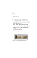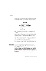
Keysight M9018A PXIe 18-Slot Chassis Startup Guide
9
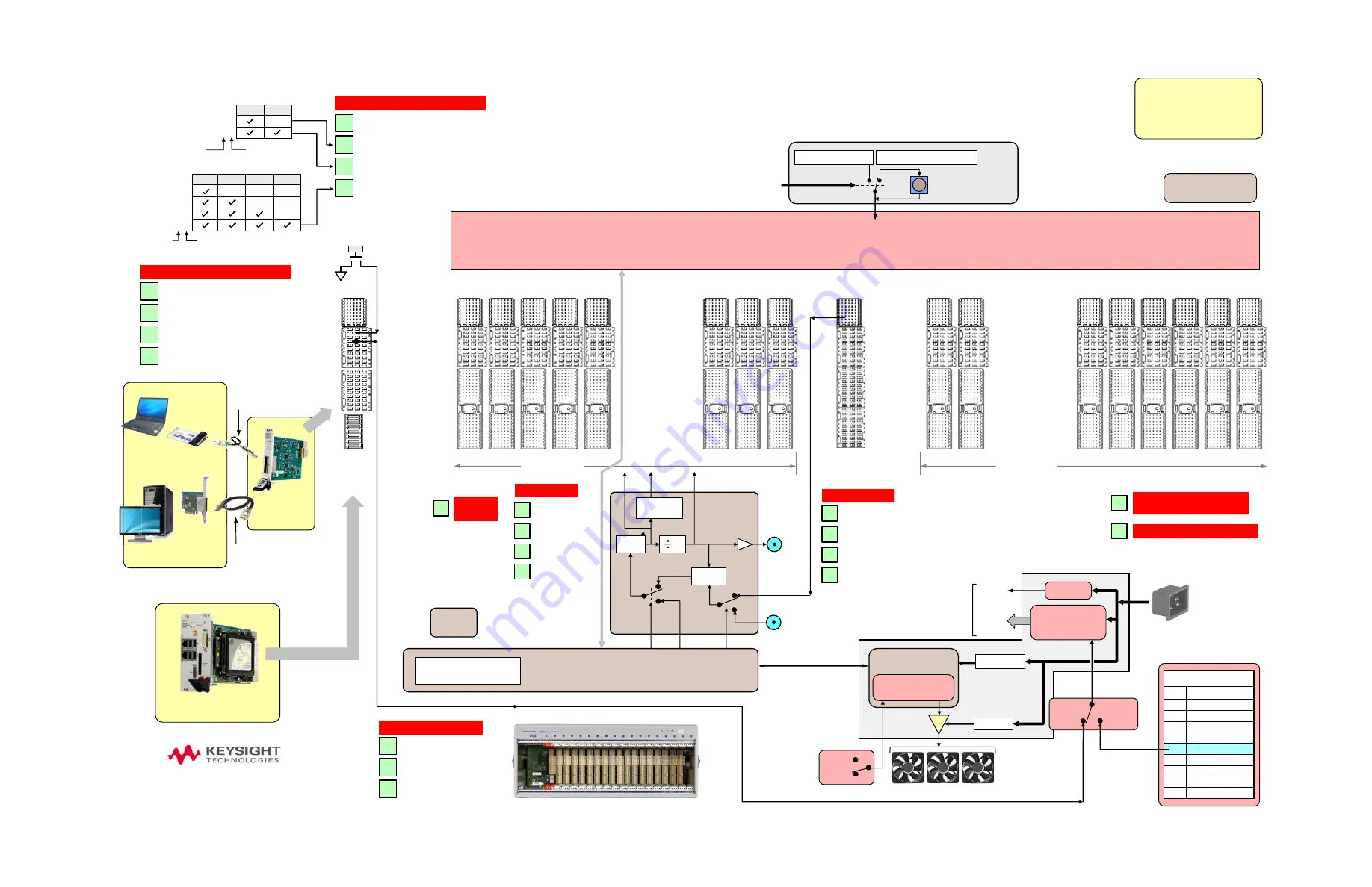
Slot 2 Slot 3 Slot 4 Slot 5 Slot 6
Slot 13 Slot 14 Slot 15 Slot 16 Slot 17
Slot 7 Slot 8 Slot 9
Slot 11 Slot 12
Slot 10
Slot 18
Slot 1
System
Controller
Slot
Hybrid Slots
M9021A PCIe
Cable
Interface (x8)
M9048A PCIe
Desktop
Adapter (x8)
Clear
1x8
2x8
4x4
System
Timing Slot
XP4
XP3
XP2
XJ1
XP4
XP3
XP1
Show Triggers
XP3
TP2
TP1
x8
PCIe Switch Fabric
x4 x4 x4
x8
x4
x4
x4
VCXO
Show Clocks
Clear
PXI_TRIG[0:7]
PXI_STAR[0:16]
PXIe_DSTAR A/B/C[0:16]
PXI_CLK10
Clock
Generator
Sync
Generator
P
X
I_CLK
10_I
N
Show
SMBus
PLL
FEEDBACK
10 MHZ REF IN
x1
x4
x8 x4
x4 x4 x8 x4 x4 x4
x1
x1
Show PCIe Link Configurations
10 MHZ
REF OUT
PLL
PXI_CLK10_IN
Front panel
ON/Standby
pushbutton
DB-9 Connector
Pin
Signal
1 Logic
ground
2 +5
VDC
3 Reserved
4 +3.3
VDC
5
Inhibit (active low)
6 +12
VDC
7 Reserved
8 -12
VDC
9 Logic
ground
Power
Supply
P
X
Ie_CLK
100
Eight backplane
temperature sensors
Remote Controllers
Hybrid Slots
M
C
In
Y1200B
PCIe cable: x1 to x8
connectors, 2.0m
Y1202A
PCIe cable: x8,
2.0m
Show Boards Supported
by the Hybrid Slots
XP4
10
Clear
PXI_CLK10
PXIe_CLK100
PXIe_SYNC100
Chassis
EPROM
INHIBIT
(rear panel)
ON
Primary
Power Module
(PPM)
3.3V
5V
12V
-12V
DEF
(default)
MAN
(manual)
5Vaux
5Vaux
PXIe_SYNC100
10 MHZ
INPUT
10 MHZ
OUTPUT
Chassis Manager
Chassis firmware
(customer upgradeable)
x1
10 MHz
Input
Select
Chassis
10 MHz
Correction
Signal
VCXO
Input
Select
(rear panel
BNC)
(rear panel BNC)
O
N/Standby
pushbutton pow
er
activ
ation signal
Show Hybrid Slot Pin Outs
PCIe Switch Fabric Configurator
This program can be used to set the
User Configuration to 2x8 or 4x4
(and point the virtual switch to the
User Configuration), or point the
switch to the Base Configuration.
Load Base
Configuration
Pushbutton
Please place your mouse
over this rounded rectangle
to view information
about this diagram.
START HERE
Embedded
Controller
Keysight
M9018A PXIe Chassis
User Configuration
Base Configuration:
1x8
User
Base
Show Chassis Views
Clear
Front
View
C20 power connector
(rear panel)
Show Host Controller Software
Clear
Keysight
Connection Expert
Soft Front Panel
Development environments
Link 1 Link 2 Link 3 Link 4
1x4
2x4
3x4
4x4
Possible
PCIe 4-Link
Configurations
Link 1 Link 2
1x8
2x8
Lanes per link
Possible
PCIe 2-Link
Configurations
Total number of
x4 links used
Links used of the four x4 links available
Lanes per link
Total number of
x8 links used
Links used of the two x8 links available
PCIe 2-Link and 4-Link Configurations
Factory
default
When the host controller PC boots, it asserts its PCIe
Reset signal which causes the User or Base Configuration
to be loaded into the PCIe Switch Fabric, depending on the
virtual switch position.
virtual switch
INHIBIT/VOLTAGE MON
(rear panel)
Monitor
Processor
Factory
default,
read-only
©
Keysight
Technologies, Inc. 2012-
2014
S
eptember 2014
M9018-90006
AUTO
HIGH
FAN
(rear panel)
Fan Monitor
and Control
Fan 12V
To module
slots and
chassis
electronics
5Vstandby
Fan assembly
ON/Standby
pushbutton
power activation
signal
Inhibit
(low = off)
PCIe
ExpressCard
Adapter (x1)

