Keysight M9018A PXIe 18-Slot Chassis Startup Guide
2
5
Chassis front panel LEDs
STEP 3: Turn On and Verify Operation of the Chassis System
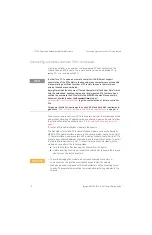
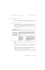
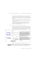
Methods of powering up the chassis
The method of powering up the chassis depends on the position of the
INHIBIT
rear panel switch, which can be set to the
DEF
(default) position or to the
MAN
(manual) position). These two methods are shown on the
on page 6 and work as follows:
- INHIBIT
switch in the
DEF
position — In this position, the front panel power
pushbutton is used to switch the chassis between ON and Standby—hence,
this pushbutton is known as the
ON/Standby pushbutton
. Using this
pushbutton requires that a module is installed in the system controller slot
(slot 1). This can be a module such as the Keysight M9021A PCIe Cable
Interface module or an embedded controller.
- INHIBIT
switch in the
MAN
position — In this position, the
Inhibit
signal on the
rear panel DB-9 connector controls chassis power. The chassis is powered up
by applying a logic high signal to the
Inhibit
signal. When the
Inhibit
signal is
low, the chassis is in Standby (off except for 5Vaux, an auxiliary power supply).
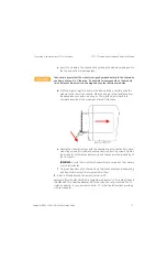
Keysight recommends leaving the
INHIBIT
switch in the
DEF
position when
connecting the AC power cord to the chassis. After inserting the power AC power
cord, then move the
INHIBIT
switch to the
MAN
position.
Use of the ON/Standby pushbutton to power up the chassis is assumed unless
otherwise noted. For information on using the
Inhibit
signal on the rear panel
DB-9 connector to power the chassis up and down, please see the M9018A User
Guide.
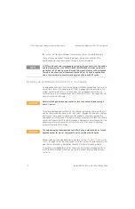
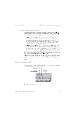
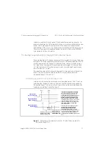
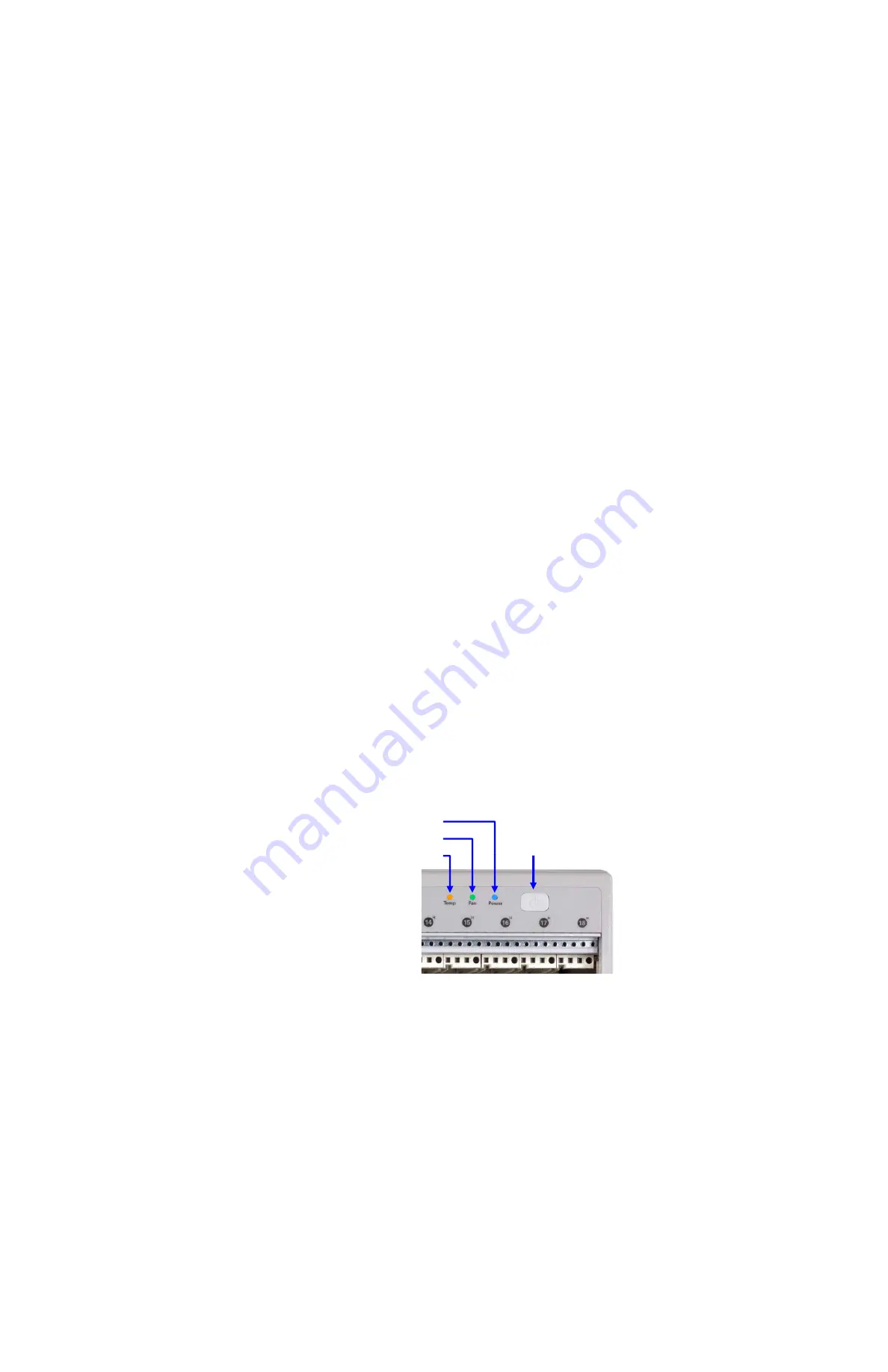
Chassis front panel LEDs
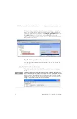
The chassis contains three LEDs on its front panel to the left of the ON/Standby
(power) pushbutton, as shown in Figure 5.
Figure 5
The three front panel LEDs
Power LED
Fan LED
Temperature LED
ON/Standby
Pushbutton
Temperature LED


