background image

Safety Information

The following general safety precau-

tions must be observed during all 

phases of operation of this instrument. 

Failure to comply with these precau-

tions or with specific warnings or oper-

ating instructions in the product 

manuals violates safety standards of 

design, manufacture, and intended use 

of the instrument. Keysight Technolo-

gies assumes no liability for the cus-

tomer's failure to comply with these 

requirements. 

General

Do not use this product in any manner not 

specified by the manufacturer. The protec-

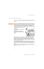
tive features of this product must not be 

impaired if it is used in a manner specified in 

the operation instructions.

Before Applying Power

Verify that all safety precautions are taken. 

Make all connections to the unit before 

applying power. Note the external markings 

described under “Safety Symbols”.

Ground the Instrument

Keysight chassis’ are provided with a 

grounding-type power plug. The 

instrument chassis and cover must be 

connected to an electrical ground to 

minimize shock hazard. The ground pin 

must be firmly connected to an electri-

cal ground (safety ground) terminal at 

the power outlet. Any interruption of 

the protective (grounding) conductor 

or disconnection of the protective 

earth terminal will cause a potential 

shock hazard that could result in per-

sonal injury.

Do Not Operate in an Explosive 

Atmosphere

Do not operate the module/chassis in 

the presence of flammable gases or 

fumes.

Do Not Operate Near Flammable 

Liquids

Do not operate the module/chassis in 

the presence of flammable liquids or 

near containers of such liquids.

Cleaning

Clean the outside of the Keysight mod-

ule/chassis with a soft, lint-free, 

slightly dampened cloth. Do not use 

detergent or chemical solvents.

Do Not Remove Instrument Cover

Only qualified, service-trained person-

nel who are aware of the hazards 

involved should remove instrument 

covers. Always disconnect the power 

cable and any external circuits before 

removing the instrument cover.

Keep away from live circuits

Operating personnel must not remove 

equipment covers or shields. Proce-

dures involving the removal of covers 

and shields are for use by service-

trained personnel only. Under certain 

conditions, dangerous voltages may 

exist even with the equipment 

switched off. To avoid dangerous elec-

trical shock, DO NOT perform proce-

dures involving cover or shield removal 

unless you are qualified to do so.

DO NOT operate damaged 

equipment

Whenever it is possible that the safety 

protection features built into this prod-

uct have been impaired, either through 

physical damage, excessive moisture, 

or any other reason, REMOVE POWER 

and do not use the product until safe 

operation can be verified by service-

trained personnel. If necessary, return 

the product to an Keysight Technolo-

gies Sales and Service Office for ser-

vice and repair to ensure the safety 

features are maintained.

DO NOT block the primary 

disconnect

The primary disconnect device is the 

appliance connector/power cord when 

a chassis used by itself, but when 

installed into a rack or system the dis-

connect may be impaired and must be 

considered part of the installation.

Do Not Modify the Instrument

Do not install substitute parts or per-

form any unauthorized modification to 

the product. Return the product to an 

Keysight Sales and Service Office to 

ensure that safety features are main-

tained.

In Case of Damage

Instruments that appear damaged or 

defective should be made inoperative 

and secured against unintended oper-

ation until they can be repaired by 

qualified service personnel.

Do NOT block vents and fan exhaust: 

To ensure adequate cooling and venti-

lation, leave a gap of at least 50mm 

(2") around vent holes on both sides of 

the chassis. 
Do NOT operate with empty slots: To 

ensure proper cooling and avoid dam-

aging equipment, fill each empty slot 

with an AXIe filler panel module.
Do NOT stack free-standing chassis: 

Stacked chassis should be rack-

mounted. 
All modules are grounded through the 

chassis: During installation, tighten 

each module's retaining screws to 

secure the module to the chassis and 

to make the ground connection.

Operator is responsible to maintain 

safe operating conditions. To ensure 

safe operating conditions, modules 

should not be operated beyond the full 

temperature range specified in the 

Environmental and physical specifica-

tion. Exceeding safe operating condi-

tions can result in shorter lifespan, 

improper module performance and 

user safety issues. When the modules 

are in use and operation within the 

specified full temperature range is not 

maintained, module surface tempera-

tures may exceed safe handling condi-

tions which can cause discomfort or 

burns if touched. In the event of a 

module exceeding the full temperature 

range, always allow the module to cool 

before touching or removing modules 

from the chassis.

iii

Summary of Contents for M9018A

Page 1: ...service in house repair center WE BUY USED EQUIPMENT Sell your excess underutilized and idle used equipment We also offer credit for buy backs and trade ins www artisantg com WeBuyEquipment REMOTE IN...

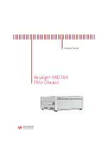
Page 2: ...Keysight M9018A PXIe Chassis Startup Guide...

Page 3: ...such license Warranty THE MATERIAL CONTAINED IN THIS DOCUMENT IS PROVIDED AS IS AND IS SUBJECT TO BEING CHANGED WITHOUT NOTICE IN FUTURE EDI TIONS FURTHER TO THE MAXIMUM EXTENT PERMITTED BY APPLICABLE...

Page 4: ...rform proce dures involving cover or shield removal unless you are qualified to do so DO NOT operate damaged equipment Whenever it is possible that the safety protection features built into this prod...

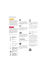
Page 5: ...evice complies with the Canadian ICES 001 This symbol represents the time period during which no hazardous or toxic substance elements are expected to leak or deteriorate during normal use Forty years...

Page 6: ...the chassis 19 M9018A PCIe Link Configuration 21 Installing software on the host controller 22 Compatibility of the M9018A Chassis Drivers with Keysight IO Libraries Suite22 Installing the Keysight IO...

Page 7: ...Guide vi 5 STEP 4 Overview of Installing and Verifying Keysight Modules Installing modules 37 Installing the module software 37 Verifying your module 37 6 Appendix A Chassis and Accessory Model Number...

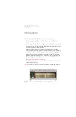
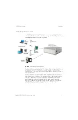
Page 8: ...ple M9018A PXIe and M9502A 2 Slot and M9505A 5 Slot AXIe chassis together all of them controlled by a single host controller The host controller can be either a PXIe Embedded Controller such as the Ke...

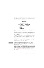
Page 9: ...ots to the left of slot 1 The combination of the chassis the host controller and a PCIe cable if the host controller is a remote controller and the chassis I O software running on the host controller...

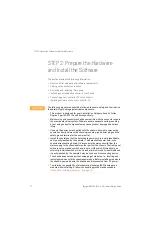
Page 10: ...luded with the chassis itself STEP 2 Prepare the Hardware and Install the Software This section describes the computer hardware and software requirements installation of an embedded controller connect...

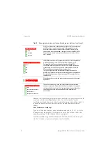
Page 11: ...so listed are the key topics covered in each group of documents Table 1 M9018A chassis documents by audience Audience Recommended Documents Key Topics First time users of the M9018A chassis M9018A Sta...

Page 12: ...terface to a remote controller a cable interface module such as the Keysight M9021A PCIe Cable Interface module is installed in slot 1 of the chassis The Keysight M9045A B PCIe ExpressCard Adapter is...

Page 13: ...ay an informational popup providing additional details Check boxes Clicking a check box will statically display additional information such as a particular PXIe switch configuration or a particular se...

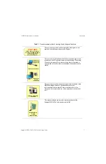
Page 14: ...to the chassis Information is also provided on the cables that are used between the adapters and the chassis Place your mouse over this rounded rectangle to view information on the M9036A Embedded Co...

Page 15: ...r all other slot 1 modules The M9018A chassis currently implements three PCIe link configurations 2 Link Configuration 1x8 2 Link Configuration 2x8 and 4 Link Configuration 4x4 These configurations pr...

Page 16: ...BNC ON Standby pushbutton power activation signal Show Hybrid Slot Pin Outs PCIe Switch Fabric Configurator This program can be used to set the User Configuration to 2x8 or 4x4 and point the virtual...

Page 17: ...ethods Conductive table mat and wrist strap combination Conductive floor mat and heel strap combination ESD protection accessories can be purchased from numerous electronics suppliers Both ESD protect...

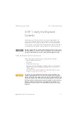
Page 18: ...are drivers and all product documentation in PDF format for the M9018A chassis Automation Ready CD with Keysight IO Libraries Suite Check for a later version at www keysight com find iosuite Keysight...

Page 19: ...d serious injury Use only the power cord supplied with the chassis Keysight power cords ensure continuity between the chassis grounding type power plug and the safety ground terminal at the power outl...

Page 20: ...d Available computer memory 1 GB minimum 1 GB minimum Available hard disk space Because of the installation procedure less memory may be required for operation than is required for installation 32bit...

Page 21: ...the captive screws should be tightened securely to ensure the filler panel is well grounded to the chassis Ensure that filler panels are installed in all empty slots Missing filler panels will impact...

Page 22: ...le Interface module in slot 1 and must be positioned to the left prior to installation of any other module including an embedded controller in slot 1 To change the position of the slide switch perform...

Page 23: ...ith the module as you perform the following steps a Turn the chassis off and unplug the chassis from AC power b Before inserting the module inspect the chassis slot to ensure there are no bent pins on...

Page 24: ...mounting screws Tighten the screws for both mechanical security and to ensure proper grounding of the front panel IMPORTANT Ensure that all empty chassis slots are covered by filler panels or air inl...

Page 25: ...ble interface module to interface to a remote controller Because the PCIe cable interface module only consumes one slot the expansion slot must be covered with the three wide filler panel to maintain...

Page 26: ...n option will work best for you The installation options include Obtain a USB interface optical drive and connect it to one of the embedded controller USB ports Copy the CD software to the embedded co...

Page 27: ...to Keysight s Multiple PXIe and AXIe Chassis Configuration tool This tool is available on the M9018A Product information CD as well as on line at www keysight com find pxie multichassis 2 Link Configu...

Page 28: ...ts of the chassis soft front panel SFP and the IVI COM IVI C LabVIEW and MATLAB drivers for the M9018A chassis These drivers each provide an API application programming interface that can be used to d...

Page 29: ...lorer to locate autorun exe at the root level of the CD and then execute that program 2 Click the Install M9018 Software link which will bring up the Keysight M9018A InstallShield Wizard 3 Click Next...

Page 30: ...a rack first please see the M9018A User Guide on the Software and Product Information CD for rack mounting information If you encounter difficulty in turning on the chassis system please see the troub...

Page 31: ...peration of the PC In brief the PC should be off whenever the chassis is powered up or down Because chassis modules are not hot swappable chassis modules should only be added or removed when the chass...

Page 32: ...edded controller INHIBIT switch in the MAN position In this position the Inhibit signal on the rear panel DB 9 connector controls chassis power The chassis is powered up by applying a logic high signa...

Page 33: ...ll return to on continuously i e the flashing state is not latched Fan LED green Typically indicates that the chassis is turned off This could also indicate a failed LED or a failure of the LED drive...

Page 34: ...arlier the PC must be restarted after Windows comes up to ensure that the chassis is recognized by Connection Expert 16 0 when it starts Figure 6 shows the complete sequence leading up to starting Con...

Page 35: ...figuration has changed This wait time is also required on the first ever boot of the PC with of the chassis This sequence is shown in Figure 7 Figure 7 Startup sequence for Connection Expert 16 1 or l...

Page 36: ...unning a chassis indicator should appear under the PXIO label in the Instrument I O on this PC pane as shown in Figure 8 in this case the chassis indicator is Chassis1 Clicking Chassis1 displays the c...

Page 37: ...nd Simulation Mode In Hardware Mode the SFP interacts with the chassis itself The SFP will display chassis information and allow you to set chassis parameters such as temperature thresholds and voltag...

Page 38: ...Then click M9018A in the M odul eslist to select it which will display M9018A in the Sel ect edI nst r umentfield Click Connectto start the SFP in Simulation Mode If a chassis has been detected M9018A...

Page 39: ...tomatically bring up the SFP in Hardware Mode because of the presence of the chassis Figure 11 Starting the SFP from Connection Expert Note that only a single instance of the SFP can be run at one tim...

Page 40: ...e 12 shows the Monitor screen of the SFP This screen displays the speed of the three fans the temperatures reported by the eight backplane temperature sensors and the four main power supply voltages T...

Page 41: ...es below 70 C The temperature alarm can be cleared using its Clear button however if any of the temperature sensors are still reporting a temperature above 70 C when the Clear button is clicked the te...

Page 42: ...lowed to ensure safety and to minimize the possibility of damaging electrical components Before installing any module in the chassis the chassis must be disconnected from AC power To minimize the poss...

Page 43: ...o be installed again when installing software for Keysight modules If you did not install IO Libraries Suite earlier it must be installed before you install your module specific software After ensurin...

Page 44: ...is and accessory model numbers Model Number Description M9018A PXIe Chassis 18 slot 3U 8 GB s opt 900 932 Power cord options M9021A PCIe Cable Interface module x8 M9045A B PCIe ExpressCard Adapter x1...

Page 45: ...rme a la norme NMB du Canada Operating conditions Indoor outdoor Ambient Temperature Humidity Altitude For indoor use only 0 C to 55 C Maximum relative humidity 80 for temperatures up to 31 C decreasi...

Page 46: ...e total power supplied for 3 3 V 12 V and 12 V rails must not exceed 616 W 4 For Keysight M9018A chassis with serial numbers before TW52460101 the maximum current allowed on the 12 V rail was 47 2 A A...

Page 47: ...rrupted No operator serviceable parts inside Refer servicing to qualified personnel To prevent electrical shock do not remove covers To prevent electrical shock disconnect the chassis power cord befor...

Page 48: ...be rack mounted as described in this chapter In preparing the chassis for rack mounting do not stand the chassis on its side the side handles can cause the chassis to tip over Depending on the power...

Page 49: ...42 Keysight M9018A PXIe 18 Slot Chassis Startup Guide Appendix B Chassis Specifications...

Page 50: ...the LXI consortium www pxisa org PCI eXtensions for Instrumentation PXI modular instrumentation delivers a rugged PC based high performance measurement and automation platform www keysight com find T...

Page 51: ...This information is subject to change without notice Keysight Technologies 2014 Edition 7 September 2014 M9018 90001 M9018 90001 www keysight com...

Page 52: ...service in house repair center WE BUY USED EQUIPMENT Sell your excess underutilized and idle used equipment We also offer credit for buy backs and trade ins www artisantg com WeBuyEquipment REMOTE IN...

Reviews: