18
Keysight PXIe System and Cable Interface Installation Guide
Step 4: Install the System or Cable Interface Module in the Chassis
Step 4: Install the System or Cable Interface Module in the Chassis
The Keysight Cable Interface Module and System Modules have been designed
for easy installation. However, the following standard precautions, installation
procedures, and general information must be observed to ensure proper
installation and to prevent damage to the board, other system components, or
injury to personnel.
Keysight’s M9021A Cable Interface Module can operate only with
the x8 switch fabric found on the M9018 chassis. It will not work on
other PXIe chassis.
The following safety precautions must be observed when installing or
operating the Keysight System Modules. Exercise care when handling the
module as the heat sink can get very hot. Do not touch the heat sink when
installing or removing the module. The board should not be placed on any
surface or in any form of storage container until the board and heat sink
have cooled to room temperature.
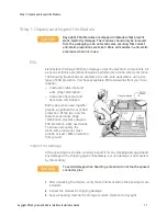
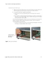
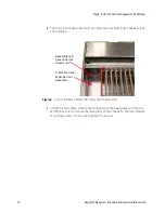
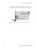
M9018A PXIe Chassis Backplane Switch for M9021A:
The M9021A Cable Interface module does not derive power from
the chassis connector used by PXI embedded controllers. Instead,
the modules use the top connector on the chassis backplane for its
3.3V and 12V power. However, a switch on the M9018A chassis
backplane must be set to supply those voltages to the connector.
The default position of the switch is to the left and does not supply
the voltages to the connector. To use the System Module or Cable
Interface module in Slot 1 of the M9018A chassis, you must move
the slide switch to the right before installing the module. Refer to
the M9018A chassis documentation for more information.
Setting this switch is not required for the M9022A, M9023A, or
M9024A.
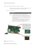
Ensure the M9018A
backplane switch is
in the right-hand position
when using the M9021A.
Summary of Contents for M9021A
Page 2: ......
Page 6: ...vi ...
Page 44: ...44 Keysight PXIe System and Cable Interface Installation Guide Troubleshooting and Service ...
Page 45: ......

