background image

Keysight PXIe System and Cable Interface Installation Guide

37

Connecting a PC to a PXIe or AXIe Chassis

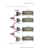
External PC to Two Chassis Configuration

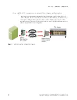
Another simple system consists of an external PC with a PCIe Host Adapter card 

(such as the Keysight M9049A) connected to two PXIe or AXIe chassis. A PXIe 

chassis requires a System Module such as the Keysight M9022A. An AXIe chassis 

does not require a system module interface, because a cable port is included in 

the ESM half height module. The link speed is determined by the chassis; for 

example, Gen 2 speed with the M9018 PXIe chassis or the M9502A or M9505A 

AXIe chassis; Gen 3 speed is available with Gen 3 PXIe chassis such as the 

M9019A.

Figure 16

Simple two chassis configuration

Summary of Contents for M9021A

Page 1: ...Keysight PXIe System Modules and Cable Interface M9021A M9022A M9023A M9024A Installation Guide ...

Page 2: ......

Page 3: ... rights in excess of these rights customarily provided to the public to use modify reproduce release per form display or disclose commercial computer software or commercial com puter software documentation No addi tional government requirements beyond those set forth in the EULA shall apply except to the extent that those terms rights or licenses are explicitly required from all providers of comme...

Page 4: ...perform proce dures involving cover or shield removal unless you are qualified to do so Do Not Operate Damaged Equipment Whenever it is possible that the safety protection features built into this prod uct have been impaired either through physical damage excessive moisture or any other reason REMOVE POWER and do not use the product until safe operation can be verified by service trained personnel...

Page 5: ... A EMC Declara tion this equipment is Class A suitable for professional use and is for use in electromagnetic environments outside of the home Waste Electrical and Electronic Equipment WEEE Directive 2002 96 EC This product complies with the WEEE Directive 2002 96 EC marking requirement The affixed product label see below indicates that you must not discard this electrical electronic prod uct in d...

Page 6: ...vi ...

Page 7: ...Interface Module Installation 23 M9021A Switch Settings 23 M9021A LEDs 24 M9022A M9023A M9024A System Module Installation 27 Understanding Features Controlled by Switch Settings 27 Mode Settings 27 Mode Host default x8 27 Mode Target x16 27 Transfer Rate Settings 28 Using the M9024A on an M9018 with 4x4 PCIe Switch Fabric 28 Module Switch Settings Summary 29 M9022A M9023A M9024A Front Panel LEDs S...

Page 8: ...viii Keysight PXIe System and Cable Interface Installation Guide Chassis Power On Generated by the Host PC 41 Module Characteristics 42 Related Products 42 Troubleshooting and Service 43 ...

Page 9: ...or x16 lanes M9024A Dual Port System Module Up to Gen 3 at 8 GT s with x8 or x16 lanes The module also has IO ports two LAN four USB 2 0 two USB 3 0 and one GPIB Each M9021A M9022A and M9023A comes complete with a 3 slot Controller Expansion Slot Blocker For installation instructions see Step 3 Install the Controller Expansion Slot Blocker on page 14 To ensure proper system operation use an approv...

Page 10: ...nnecting a PC to a PXIe or AXIe Chassis on page 36 For additional information on using these chassis inter connection components see the Keysight Multi chassis Designer found at www keysight com find pxie multichassis or by searching on the document name System Limitations Enumeration Limitations All of the modules can be used with embedded controllers or external PCs However PCs are not equal in ...

Page 11: ...ovides adequate ESD protection when used alone To ensure user safety the static safe accessories must provide at least 1 M of isolation from ground Inspect for damage After unpacking the module carefully inspect it for any shipping damage Report any damage to the shipping agent immediately as such damage is not covered by the warranty 1 After unpacking the module verify that all items listed on th...

Page 12: ...ww keysight com find M9021A 3 Write the following information on a tag and attach it to the malfunctioning equipment Name and address of owner A Post Office box is not acceptable as a return address Product model number for example M9021A Product serial number for example TWXXXXXXXX The serial number label is located on the side of the module A description of failure or service required 4 Carefull...

Page 13: ...stallation information A single driver install utility services the M9022A M9023A and M9024A modules It is available on the software CD as well as on each of the Keysight product web sites www keysight com find M9022A www keysight com find M9023A www keysight com find M9024A The most current version of Keysight IO Libraries is required prior to installing and running any other software The latest ...

Page 14: ...he Controller Expansion Slot Blocker provides one 3 slot blocker baseplate and cover with captive screws and two M3 Phillips screws See below For proper chassis air flow and module cooling all slots in the PXI chassis must be populated with either a PXI module a Slot Blocker Y1212A covered with a filler panel or have an Air Inlet Module installed Y1214B For additional chassis cooling information s...

Page 15: ...t of the red slot guides b Note that the Controller Expansion Slot Blocker consists of a base plate a front plate and two M3 Phillips screws Install the base plate in the chassis before you attach the face plate In the following photographs chassis covers and all modules were removed for clarity You do not need to remove modules or chassis covers to install the Controller Expansion Slot Blocker c ...

Page 16: ...um chassis rail as shown below e Install the face plate Secure the face plate to the base plate with the two M3 Phillips screws Secure the face plate to the chassis by the four module mounting screws Do not over tighten the screws Figure 3 Locate the Base Plate Tab under the Chassis Rail Base Plate tab goes under the chassis rail 3 Slot Controller Expansion Sot Base Plate ...

Page 17: ...gure 4 Secure the Front Cover Secure the top screws to the chassis rails Install the two supplied M3 Phillips screws Secure the bottom screws to the chassis rails Install all chassis covers and slot blockers Install the other PXIe modules Missing filler panels may disrupt necessary chassis air circulation for additional cooling information see the white paper at https literature cdn keysight com l...

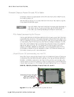
Page 18: ...Do not touch the heat sink when installing or removing the module The board should not be placed on any surface or in any form of storage container until the board and heat sink have cooled to room temperature M9018A PXIe Chassis Backplane Switch for M9021A The M9021A Cable Interface module does not derive power from the chassis connector used by PXI embedded controllers Instead the modules use th...

Page 19: ...it Technical Support Drivers Firmware Software Select the M902x driver Follow the on screen instructions to install the driver on your host PC The M9021A Cable Interface Module does not require a driver If the driver installation does not detect an M902x module it will display the following message Click Yes to continue the installation M9024A Driver Installation Have the M9024A in the chassis whe...

Page 20: ...M9010A and M9019A chassis is fixed so there is no need to configure the chassis switch fabric when using the M9022A M9023A or M9024A system modules General Installation Considerations The following table shows which PXIe chassis slots the System Modules or M9021A Cable Interface module may be installed in For a full discussion of PCIe link configuration see the topic Viewing the PCIe Link Configur...

Page 21: ...ystem Module are set correctly a Refer to M9021A Switch Settings on page 23 for information on the M9021A switches b Refer to Module Switch Settings Summary on page 29 for information on the System Module switches 5 Remove the screw protection caps from the module retaining screws 6 Push down on the module s ejector injector handle 7 Carefully align the module board edges with the chassis guide ra...

Page 22: ...ng With the keyed slot aligned with the key ridge on the PCIe adapter insert the cable connector into the cable port connector on the adapter until the cable locks in place 13 Attach the other end of the cable to the PCIe adapter on your Host computer 14 Power up the PXIe chassis Verify that the chassis fans are operating and free of obstructions that may restrict air flow 15 Power up the Host PC ...

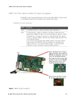
Page 23: ...l the M9021A in the system slot slot 1 of the M9018A PXIe chassis The two switches on S301 must be in the Target right position This is the default setting For connecting to a downstream RAID solution such as the JMR mass storage the M9021A must be installed in a x8 hybrid slot either slot 2 6 11 or 15 in the PXIe chassis In this case both switches on S301 should be in the Host left position Figur...

Page 24: ... front panel has four LEDs to indicate the communication speed to the host controller The following table describes the LED indications If you remove a slot 2 module or filler panel to view the M9021A LEDs ensure that the module or filler panel is reinstalled This is required to maintain chassis cooling as well as minimize radio frequency interference Configuration to Host PC M9021A Front Panel LE...

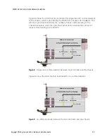
Page 25: ...inated for x4 communications Figure 8 Single lane communications between host controller and the chassis Figure 9 x4 communications between the host controller and the chassis M9021A Cable Interface Module An ON LED indicates that the lane is active based on the card detecting that the lane s receiver is enabled 7 7 CABLE LANE DETECT 4 5 6 7 4 5 6 BACK PLANE LANE DETECT CABLE LANE DETECT 1 2 3 Lan...

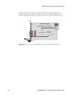
Page 26: ...an eight lane M9048A PCIe Desktop Adapter installed in an x8 mode x8 slot or in an x16 mode x16 slot Figure 10 x8 communications between the host controller and the chassis M9021A Cable Interface Module An ON LED indicates that the lane is active based on the card detecting that the lane s receiver is enabled 7 7 CABLE LANE DETECT 4 5 6 7 4 5 6 BACK PLANE LANE DETECT CABLE LANE DETECT 1 2 3 Lane n...

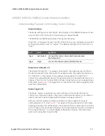
Page 27: ...evice for example when the downstream device is a chassis PCIe Port 2 is the host Both of these connections will use a single 8 lane PCIe cable See Figure 19 on page 40 for an example PCIe cable topography that uses this configuration Mode Target x16 The mode target is possible via switch settings In this mode PCIe Port 2 connects to a upstream device There are no downstream devices This mode is u...

Page 28: ...und or diagnostics debug step you can throw the switches on the M9022A M9023A and M9024A modules to lower the maximum speed to Gen 1 This lower speed may allow the device to function reliably For these devices the Gen1 speed is usually not a throughput performance bottleneck Using the M9024A on an M9018 with 4x4 PCIe Switch Fabric M9024A can be used in an M9018 or M9019A PXIe Chassis The M9018 can...

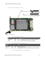
Page 29: ...position Figure 11 Switch Settings SW1 Default Host mode Gen 3 Low High Low High SW1 Target mode Gen 3 Mode 1 2 Used for Host default Target High High Low High x8 single PCIe cable to chassis for multi chassis Cascade or Star x16 two PCIe cables to chassis for multi chassis Star PCIe Link Speed 3 4 Used for Gen 3 default Gen 1 High High High Low Normal high speed operation Slower speed operation t...

Page 30: ...f No Power Red Power Supply problem or FPGA normal to go briefly Red on power up and power down Blue Module okay but no link present Green Link present Status of Host connection Off No link present White Gen 1 Connection Blue Gen 2 Connection Green Gen 3 Connection Status of backplane connection Top LED is Link 1 status Bottom LED is Link 2 status Off No link present White Gen 1 Connection Blue Ge...

Page 31: ...5 D14 D17 D9 D23 D13 D12 D11 D10 D32 D31 LED Indicates D17 PXI power is okay D14 0 9 VDC power is okay D15 1 8 VDC power is okay D9 FPGA configuration is okay D23 PCIe link status for FPGA D10 D13 PCIe Link Status when the backplane is 4 link routing When the backplane is 2 link routing D10 indicates PCIe link status for left side mezzanine board D31 D32 PCIe Link Status when the backplane is 2 li...

Page 32: ...allation Guide M9022A M9023A M9024A System Module Installation On the backside of the M9024A module are two LEDs Figure 14 Back of M9024A module showing two LEDs LED Indicates D3 Configuration is okay for GPB controller D4 1 0 VDC power is okay D4 D3 ...

Page 33: ...mpatible with USB 2 0 devices however data transfer speeds are limited to USB 2 0 levels when these devices inter operate USB 2 0 USB 3 0 Backwards Compatibility USB 1 1 USB 1 1 and USB 2 0 data transfer speeds are limited to USB 1 1 or USB 2 0 levels Speed 480 Mbps known as High Speed HS 10 times faster than USB 2 0 Super Speed or SS 4 8 Gbps Signaling Method Half duplex Full duplex Asynchronous ...

Page 34: ...ments The on board GPIB controller has the following features Compatible with the IEEE 488 standard Up to 1 5MB s data transfer rates On board 2 KB FIFO for read write operations Connect up to 14 instruments GPIB is a standard VISA Resource Activity LED No Link Link Established Link established and Network activity Off On Amber LED flashes Amber Speed LED No Link 10 Mbps 100 Mbps 1 Gba Off Off On ...

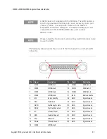
Page 35: ... number M9036 31301 Please install the most recent version of Keysight IO Libraries Suite to use the GPIB Pin Signal Description Pin Signal Description 1 DIO1 GPIB Data 1 14 DIO6 GPIB Data 6 2 DIO2 GPIB Data 2 15 DIO7 GPIB Data 7 3 DIO3 GPIB Data 3 16 DIO8 GPIB Data 8 4 DIO4 GPIB Data 4 17 REN Remote Enable 5 EOI End or Identify 18 GND Signal Ground 6 DAV Data Valid 19 GND Signal Ground 7 NRFD Not...

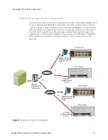
Page 36: ... with a PCIe Host Adapter card such as the Keysight M9048B connected to a PXIe or AXIe chassis A PXIe chassis requires a System Module or Cable Interface Module such as the Keysight M9021A An AXIe chassis does not require a system module interface because a cable port is included in the ESM half height module To ensure proper system operation use an approved host computer embedded rackmount deskto...

Page 37: ...d to two PXIe or AXIe chassis A PXIe chassis requires a System Module such as the Keysight M9022A An AXIe chassis does not require a system module interface because a cable port is included in the ESM half height module The link speed is determined by the chassis for example Gen 2 speed with the M9018 PXIe chassis or the M9502A or M9505A AXIe chassis Gen 3 speed is available with Gen 3 PXIe chassi...

Page 38: ...lowing configuration represents the fastest speed x16 between the PC and the chassis Make certain that all switches on the interface modules are set correctly to configure this operation Make certain the top connector on the M9049A module connects to the top connector on the M9023A module and the bottom connectors connect together Figure 17 x16 Connection to the PXIe chassis ...

Page 39: ...ght PXIe System and Cable Interface Installation Guide 39 Connecting a PC to a PXIe or AXIe Chassis M9037A Embedded Controller to Second Chassis Figure 18 M9037A Embedded Controller to a second PXIe chassis ...

Page 40: ...Keysight PXIe System and Cable Interface Installation Guide Connecting a PC to a PXIe or AXIe Chassis M9037A Embedded Controller to Cascade of PXIe Chassis Figure 19 Cascade or Daisy Chain of PXIe Chassis ...

Page 41: ... For information on the Keysight PCIe Host Adapters M9048A M9048B and M9049A see the Keysight Remote PC PCIe Host Desktop Adapter Modules Installation Guide For information about your PC s BIOS consult your PC s documentation Chassis Power On Generated by the Host PC When the chassis receives the Chassis Power On CPWRON signal its behavior is determined by the CPWRON switch setting on the System M...

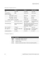
Page 42: ...nector One x8 PCIe IPASS cable connector Two x8 PCIe IPASS cable connector Front panel indicators LEDs for PCIe lane status and link size Power Present indicator orange power up Green power up and link partner present Speed indicator Green LED Gen3 solid Gen2 2 Hz blink Gen1 1 Hz blink Power consumption 5 W typical 15 W 16 W 18 W Cable length max Up to 2 meter passive cable supported Up to 5 meter...

Page 43: ...t controller PC A faulty PCIe cable A failure of the chassis power supply If power is applied and the switches are set correctly and either the LEDS are not lit or are lit incorrectly the module may be defective Replacement part numbers are as follows A download able driver may be required for the M9022A M9023A and M9024A modules Refer to Step 5 Install the Driver on page 19 for driver installatio...

Page 44: ...44 Keysight PXIe System and Cable Interface Installation Guide Troubleshooting and Service ...

Page 45: ......

Page 46: ...This information is subject to change without notice Keysight Technologies 2015 2019 Third Edition January 2019 Printed in Malaysia M9022 90001 M9022 90001 www keysight com ...

Reviews: