background image

Module Functional Description

30

Keysight M9180 Series Startup Guide

THIS PAGE HAS BEEN INTENTIONALLY LEFT BLANK.

Summary of Contents for M9180 Series

Page 1: ...Keysight M9180 Series PXI 6 Digit Digital Multimeters M9181A M9182A M9183A Startup Guide ...

Page 2: ...ghts customarily provided to the public to use modify reproduce release per form display or disclose commercial computer software or commercial com puter software documentation No additional government requirements beyond those set forth in the EULA shall apply except to the extent that those terms rights or licenses are explicitly required from all providers of commercial computer software pursu ...

Page 3: ...ademarks of Microsoft Corporation MATLAB is a U S registered Trademark of The MathWorks Inc PXI is a registered trademark of the PXI Systems Alliance Visual Studio is a registered trademark of Microsoft Corporation in the United States LabVIEW is a registered trademark of National Instruments ...

Page 4: ...afe operation of the instrument Caution risk of danger refer to this manual for specific Warning or Caution information Earth ground terminal Alternating current AC Frame or chassis ground terminal Direct current DC Standby Power Unit is not completely disconnected from AC mains when power switch is in standby position Indicates that antistatic precautions should be taken ...

Page 5: ...paired if it is used in a manner specified in the operation instructions Before applying power Verify that all safety precautions are taken Make all connections to the unit before applying power Note the instrument s external markings described under Safety Symbols Ground the instrument PXI chassis are provided with a grounding type power plug The instrument chassis and cover must be connected to ...

Page 6: ...nnel must not remove equipment covers or shields Procedures involving the removal of covers and shields are for use by service trained personnel only Under certain conditions dangerous voltages may exist even with the equipment switched off To avoid dangerous electrical shock DO NOT perform procedures involving cover or shield removal unless you are qualified to do so Do not operate damaged equipm...

Page 7: ...ive and secured against unintended operation until they can be repaired by qualified service personnel WARNING IEC Measurement Category II The HI and LO input terminals may be connected to mains in IEC Category II installations for line voltages up to 300 VAC To avoid the danger of electric shock do not connect the inputs to mains for line voltages above 300 VAC The M9181A DMM is limited to 240 VA...

Page 8: ...uch devices or to the branch outlet itself up to 300 VAC or 240 VAC for the M9181A However the DMMs may not be used with their HI and LO inputs connected to mains in permanently installed electrical devices such as the main circuit breaker panel sub panel disconnect boxes or permanently wired motors Such devices and circuits are subject to overvoltages that may exceed the protection limits of the ...

Page 9: ...tives This is the symbol for an Industrial Scientific and Medical Group 1 Class A product ICES NMB 001 indicates that this ISM device complies with the Canadian ICES 001 Cet appareil ISM est conforme a la norme NMB 001 du Canada The RCM mark is a registered trademark of the Australian Communications and Media Authority RECOGNIZED COMPONENT Conforms to UL STD 61010 1 Certified to CSA STD C22 2 No 6...

Page 10: ... product label is as shown below Do not dispose in domestic household waste To return this unwanted instrument contact your nearest Keysight Service Center or visit http about keysight com en companyinfo environment takeback shtml for more information Sales and Technical Support To contact Keysight for sales and technical support refer to the support links on the following Keysight websites www ke...

Page 11: ...connect 7 Do not modify the instrument 7 In case of damage 7 IEC Measurement Category II overvoltage protection 8 Regulatory Markings 9 Waste Electrical and Electronic Equipment WEEE Directive 10 Product category 10 Sales and Technical Support 10 Introduction 13 Related documentation 13 Step 1 Unpack and Inspect the Module 14 Step 2 Verify Shipment Contents 16 Step 3 Install the Software on the Co...

Page 12: ...tup Guide Using a remote PC 22 Using an embedded computer 23 Step 5 Install the DMM Modules in the PXI Chassis 24 Step 6 Verify Operation of the DMM 26 Run Keysight IO Libraries Connection Expert 26 Module Functional Description 29 ...

Page 13: ... you to support the modules in many popular PXI chassis and programming environments The soft front panel allows you to exercise the DMMs Related documentation This Startup Guide and the documentation listed below can be found on the Keysight M9180 Series PXI Digital Multimeters Software and Product Information CD that came with your module Help file for the Keysight PXI DMM Modules Soft Front Pan...

Page 14: ...rotection when used alone To ensure user safety the static safe accessories must provide at least 1 MΩ of isolation from ground Inspect for damage After unpacking the DMM carefully inspect it for any shipping damage Report any damage to the shipping agent immediately as such damage is not covered by the warranty CAUTION Keysight s PXI DMMs are shipped in materials which prevent static electricity ...

Page 15: ...find pxi dmm 3 Write the following information on a tag and attach it to the malfunctioning equipment Name and address of owner A Post Office box is not acceptable as a return address Product model number for example M9182A Product serial number for example MYXXXXXXXX The serial number label is located on the side of the module A description of failure or service required 4 Carefully pack the modu...

Page 16: ...cument Keysight M9180 Series PXI 6 Digit Digital Multimeters Startup Guide in hard copy The Keysight M9180 Series PXI Digital Multimeters Software and Product Information CD M9182 10001 This CD contains software drivers and all product printed documentation in PDF format for the PXI DMMs An Automation Ready CD with Keysight IO Libraries Suite Any other accessories that you ordered cables connector...

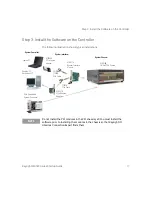
Page 17: ...stem Interface Module M9018B 18 Slot PXIe Chassis Y1202A PCIe Cable Y1200A PCIe Cable PXIe Embedded System Controller M9047A PCIe Desktop Adapter Desktop PC Rackmount PC Laptop PC System Controller System Chassis System Interface NOTE Do not install the PXI modules in the PXI chassis yet You must install the software prior to installing the modules in the chassis so that Keysight IO Libraries Conn...

Page 18: ... 1 GHz 32 bit x86 1 GHz 64 bit x64 no support for Itanium64 or Windows 8 RT Available memory 1 GB minimum 1 GB minimum 1 GB minimum Available hard disk space a 1 5 GB available hard disk space includes 1 GB available for Microsoft NET Framework 4 6 100MB for Keysight IO Libraries Suite 2 5 GB available hard disk space includes 2 GB available for Microsoft NET Framework 3 5 and 4 6 100MB for Keysig...

Page 19: ...rals such as a mouse keyboard monitor CD ROM drive etc 3 Power up the chassis 4 Choose the automatic option for any Found Hardware dialogs Install Keysight IO Libraries Suite Install Keysight IO Library Suite IOLS which includes the Keysight Connection Expert the IVI Shared Components and the VISA Shared Components 1 Insert the Automation Ready CD with Keysight IO Libraries Suite into the CD ROM d...

Page 20: ...de to connect to the switches Accept the license terms and click Next Keysight IVI Driver Source Code License Agreement The Interchangeable Virtual Instrument IVI driver is available for programming the Keysight switch modules using Microsoft development environments e g Visual Studio C C C Visual Basic Keysight VEE MATLAB or National Instruments LabVIEWTM Accept the license terms and click Next K...

Page 21: ...r software is ready to be installed on your host computer Click Install 6 The installation program will take several minutes to finish the installation do not cancel the installation process When the installation wizard is finished you will be prompted to reboot your host computer Do not reboot the host computer at this time Select No I will restart my computer later Power down the host computer N...

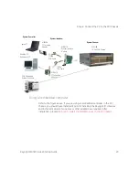
Page 22: ... a desktop or rackmount PC install the M9047 PCIe Desktop Adapter in the PC With an Keysight Y1202 cable connect the adapter to the System Interface module If you are using a laptop PC then install the M9045 PCIe ExpressCard Adapter in the laptop PC With an Keysight Y1200 cable connect the adapter to the System Interface module or the embedded computer on the PXI chassis NOTE To ensure proper oper...

Page 23: ...ing the Keysight IO Libraries and instrument drivers No cables or other adapters are required After installation proceed to Step 5 Install the DMM Modules in the PXI Chassis M9045A PCIe Laptop Adapter M9021A System Interface Module M9018B 18 Slot PXIe Chassis Y1202A PCIe Cable Y1200A PCIe Cable PXIe Embedded System Controller M9047A PCIe Desktop Adapter Desktop PC Rackmount PC Laptop PC System Con...

Page 24: ...all the module into the PXI slot of the chassis by placing the module card edges into the front module guides top and bottom Slide the module to the rear of the chassis and assure that the injector ejector handle is pushed down in the unlatched downward position CAUTION PXI hardware does not support hot swap capabilities changing modules while power is applied to the chassis Before installing Keys...

Page 25: ...the screws on the module or remote controller front panel Performance may suffer if the screws are not securely tightened 7 Install all chassis covers filler panels and air scoops after installing the module Missing filler panels may disrupt necessary air circulation in the chassis 8 If you are using a remote controller connect the Cable Interface Card in the chassis to host computer 9 Plug in and...

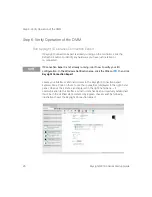
Page 26: ... Keysight Connection Expert Explorer Pane Click on them to see their properties displayed in the right hand pane Observe their state also displayed in the right hand pane if communication to the interface or instrument has been successfully established it will be in the Verified state denoted by a green check mark The following illustration shows the Keysight Connection Expert NOTE If Connection E...

Page 27: ...duct Information CD for specific detailed information on using the SFP The following graphic shows an example of the SFP for the DMM modules Verify operation To verify basic operational readiness use the Soft Front Panel software to configure and take a few basic measurements For example you could apply a short across the input terminals and take a DCV measurement or 2W Ω measurement Both measurem...

Page 28: ...Step 6 Verify Operation of the DMM 28 Keysight M9180 Series Startup Guide ...

Page 29: ...e single slot 3U height 128 mm Eurocard standard These modules meet PXI Specification 2 2 Local bus trigger bus and star trigger are not included The modules also include CPCI Ejector Handle The front panel secures to the chassis by two M2 5 6 mm pan head Posi drive screws There are no user serviceable or field replaceable components on these modules ...

Page 30: ...Module Functional Description 30 Keysight M9180 Series Startup Guide THIS PAGE HAS BEEN INTENTIONALLY LEFT BLANK ...

Page 31: ... is subject to change without notice Always refer to the Keysight website for the latest revision Keysight Technologies 2011 2017 Edition 4 November 30 2017 Printed in Malaysia M9182 90001 M9182 90001 www keysight com ...

Reviews: