background image

Calibration

56

Keysight M9182A/M9183A Calibration and Verification Procedure

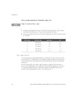
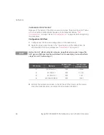
SFP Cal step

Function

Range (

W

)

Input level

Input function

2W/4W 

W

43

DCI Source

IE-06

A

2W

1,000,000

44

Ohm-4W Gain

20

4W

19

45

Ohm-4W Gain

200

4W

190

46

Ohm-4W Gain

2,000

4W

1,900

47

Ohm-4W Gain

20,000

4W

19,000

48

Ohm-4W Gain

200,000

4W

190,000

49

Ohm-4W Gain

2,000,000

4W

1,900,000

50

Ohm-4W Gain

20,000,000

4W

19,000,000

51

Ohm-2W Gain

200,000,000

2W

100,000,000

52

Ohm-2W Gain

20

2W

19

Summary of Contents for M9181A

Page 1: ...Keysight M9182A M9183A PXI 6 Digit Multimeter Calibration and Verification Procedure ...

Page 2: ...these rights customarily provided to the public to use modify reproduce release per form display or disclose commercial computer software or commercial com puter software documentation No additional government requirements beyond those set forth in the EULA shall apply except to the extent that those terms rights or licenses are explicitly required from all providers of commercial computer softwar...

Page 3: ...ight M9182A M9183A Calibration and Verification Procedure 3 Trademarks Microsoft and Windows are U S registered trademarks of Microsoft Corporation PXI is a registered trademark of the PXI Systems Alliance ...

Page 4: ...to maintain safe operation of the instrument Caution risk of danger refer to this manual for specific Warning or Caution information Earth ground terminal Alternating current AC Frame or chassis ground terminal Direct current DC Standby Power Unit is not completely disconnected from AC mains when power switch is in standby position Indicates that antistatic precautions should be taken ...

Page 5: ...ust not be impaired if it is used in a manner specified in the operation instructions Before Applying Power Verify that all safety precautions are taken Make all connections to the unit before applying power Note the instrument s external markings described under Safety Symbols Ground the Instrument PXI chassis are provided with a grounding type power plug The instrument chassis and cover must be ...

Page 6: ...erating personnel must not remove equipment covers or shields Procedures involving the removal of covers and shields are for use by service trained personnel only Under certain conditions dangerous voltages may exist even with the equipment switched off To avoid dangerous electrical shock DO NOT perform procedures involving cover or shield removal unless you are qualified to do so DO NOT Operate D...

Page 7: ...made inoperative and secured against unintended operation until they can be repaired by qualified service personnel WARNING IEC Measurement Category II The HI and LO input terminals may be connected to mains in IEC Category II installations for line voltages up to 300 VAC To avoid the danger of electric shock do not connect the inputs to mains for line voltages above 300 VAC The M9181A DMM is limi...

Page 8: ...to mains in such devices or to the branch outlet itself up to 300 VAC or 240 VAC for the M9181A However the DMMs may not be used with their HI and LO inputs connected to mains in permanently installed electrical devices such as the main circuit breaker panel sub panel disconnect boxes or permanently wired motors Such devices and circuits are subject to overvoltages that may exceed the protection l...

Page 9: ...n Legal Directives This is the symbol for an Industrial Scientific and Medical Group 1 Class A product ICES NMB 001 indicates that this ISM device complies with the Canadian ICES 001 Cet appareil ISM est conforme a la norme NMB 001 du Canada The RCM mark is a registered trademark of the Australian Communications and Media Authority RECOGNIZED COMPONENT Conforms to UL STD 61010 1 Certified to CSA S...

Page 10: ...t The affixed product label is as shown below Do not dispose in domestic household waste To return this unwanted instrument contact your nearest Keysight Service Center or visit http about keysight com en companyinfo environment takeback shtml for more information Sales and Technical Support To contact Keysight for sales and technical support refer to the support links on the following Keysight we...

Page 11: ...ment 6 DO NOT Block the Primary Disconnect 7 Do Not Modify the Instrument 7 In Case of Damage 7 IEC Measurement Category II Overvoltage Protection 8 Regulatory Markings 9 Waste Electrical and Electronic Equipment WEEE Directive 10 Product category 10 Sales and Technical Support 10 Verification 13 Performance Verification Tests 14 Input Connections 16 Test Considerations 16 Null Measurement 17 Test...

Page 12: ... Services 37 Calibration Interval 37 Automating Calibration Procedures 38 Calibration Message and Calibration Count 38 Calibration Process 39 Calibration Adjustment Process 40 Storing the Calibration Constants 41 Aborting a Calibration in Progress 41 Adjustments 41 Securing the Calibration Memory after Calibration 42 Zero and ADC Adjustment 42 Calibration Steps 43 Gain Adjustments 44 Calibration o...

Page 13: ...d equipment Accuracy requirements DC Voltage Fluke 5720A 1 5 instrument 24 hour spec DC Current Fluke 5720A 10 MW Resistor a a 10 MΩ resistor 25 ppm C 250 V measured by Keysight 3458A or equivalent 1 5 instrument 24 hour spec Resistance Fluke 5720A 1 5 instrument 24 hour spec AC Voltage Fluke 5720A 1 5 instrument 24 hour spec AC Current Fluke 5720A 1 5 instrument 24 hour spec Frequency Fluke 5720A...

Page 14: ...ensive set of tests that are recommended as an acceptance test when you first receive the instrument or after performing adjustments These three levels of performance verification are described below Self Test The DMM automatically runs a brief power on self test whenever you turn on the instrument This limited test assures that the instrument is capable of operation but it does not verify that me...

Page 15: ...ck performance check do the following Perform a self test from the Tools menu on the Soft Front Panel Perform the performance verification tests indicated with the letter Q If the DMM fails the quick performance check adjustment or repair is required Performance Verification Tests The performance verification tests are recommended as acceptance tests when you first receive the instrument The accep...

Page 16: ...erformed at 23 C 2 C Ensure ambient relative humidity is less than 80 Allow a 60 minute warmup period with a copper short connected to the voltage input terminals Use shielded twisted pair Teflon insulated cables to reduce settling and noise errors Keep the input cables as short as possible Connect the input cable shields to earth ground Except where noted in the procedures connect the calibrator ...

Page 17: ...st most sensitive range on DCV and OHMS functions and providing a copper short on the input terminals For the DCI function the input terminals should be left with no connection 1 Set the Soft Front Panel to continuous trigger by clicking the Continuous button 2 Set the Function and Range 3 Press Null The next reading taken by the DMM will become the null value All subsequent measurements taken on ...

Page 18: ...d make all DCV measurement in the following table nulled to this measurement See Null Measurement above 4 On the M9182A 83A DMM select each function and range in the order shown in thefollowing table Using the calibrator provide the input shown in the same table 5 Make a DC voltage measurement on the M9182A 83A DMM and return the result Compare measurement results to the appropriate test limits sh...

Page 19: ...E 06 9 6E 06 12E 06 2 000000E 00 DCV 2 000000E 00 44E 06 64E 06 86E 06 000 0000E 00 DCV 2 000000E 00 4E 06 4E 06 6E 06 2 000000E 0 0 DCV 2 000000E 00 Q 44E 06 64E 06 86E 06 20 00000E 00 DCV 20 00000E 00 920E 06 1 14E 03 1 56E 03 000 0000E 00 DCV 20 00000E 00 120E 06 140E 06 160E 06 20 00000E 0 0 DCV 20 00000E 00 920E 06 1 14E 03 1 56E 03 200 0000E 00 DCV 200 0000E 00 Q 6 4E 03 8 2E 03 10 6E 03 000...

Page 20: ... and range in the order shown below Using the calibrator provide the input shown in the table below 5 Make a DC current measurement on the M9182A 83A DMM and return the result Compare measurement results to the appropriate test limits shown in the table Be certain to allow for appropriate source settling when using the Fluke 5720A Calibrator input current A DMM function DMM range A Quick check Err...

Page 21: ...lowing measurements nulled to the above measurement 4 Connect the calibrator to the Current input terminals of the DMM as shown below 5 Select the 200 μA range on the M9182A 83A DMM and apply 200 μA to the current input terminals from the calibrator 6 Make a DC current measurement on the M9182A 83A DMM and return the result Compare measurement results to the appropriate test limits shown in the ta...

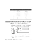
Page 22: ...onnect the 10 MΩ to the high output of the calibrator voltage terminal 5 Connect the other side of the 10 MΩ resistor to the HI current input of the M9182A 83A DMM 6 Connect the voltage low of the calibrator to the LO current input terminal The connections in this step and the previous two steps are shown in the figure below 7 Program the calibrator to DCV value Irange Value of 10 MΩ resistor 8 Ma...

Page 23: ...value programmed is 200e 9 10 02000e6 2 004 V WARNING Any voltages greater than 42 V may present a safety hazard Make certain that these voltages are not accessible Calibrator source voltage Calibrator source IRange A DMM function DMM range A Quick check Error from nominal A 24 hours 90 days 1 year 200 0000E 06 DCI 200 0000E 06 Q 304 0E 09 440 0E 09 600 0E 09 Irange Measured 10M 20 00000E 06 DCI 2...

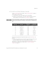
Page 24: ...rator to the input terminals of the DMM using all four wires as shown below 5 Perform a null measurement with the calibrator programmed to 0 Ω and the DMM on the lowest range Perform the 4 wire ohms measurements below on the M9182A 83A DMM nulled to this measurement 6 Select each range in the order shown below Using the calibrator provide the resistance value indicated Compare measurement results ...

Page 25: ...03 1 900000E 03 4W W 2 000000E 03 Q 97E 03 192E 03 268E 03 000 0000E 00 4W W 20 00000E 03 400E 03 400E 03 400E 03 19 00000E 03 4W W 20 00000E 03 970E 03 1 92E 00 2 68E 00 000 0000E 00 4W W 200 0000E 03 4 0E 00 4 0E 00 4 0E 00 190 0000E 03 4W W 200 0000E 03 15 4E 00 23 0E 00 36 4E 00 000 0000E 00 4W W 2 000000E 06 Q 40E 00 60E 00 60E 00 190 0000E 03 4W W 2 000000E 06 382E 00 630E 00 820E 00 000 000...

Page 26: ...erminals of the DMM as shown below 4 On the calibrator select 2 wire compensation 5 Perform a null measurement with 0 Ω from the calibrator All 2 wire ohms measurements are now made relative to this null to remove the lead resistance 6 Select each range in the order shown below Using the calibrator provide the resistance value indicated Compare measurement results to the appropriate test limits sh...

Page 27: ...0 0000E 00 2W W 200 0000E 00 12 6E 03 24 0E 03 31 7E 03 1 900000E 03 2W W 2 000000E 03 98E 03 193E 03 269E 03 19 00000E 03 2W W 20 00000E 03 Q 971E 03 1 921E 00 2 681E 00 190 0000E 03 2W W 200 0000E 03 15 4E 00 23 0E 00 36 4E 00 1 900000E 06 2W W 2 000000E 06 382E 00 630E 00 820E 00 19 00000E 06 2W W 20 00000E 06 23 20E 03 25 30E 03 38 60E 03 100 0000E 06 2W W 200 0000E 06 a 826 0E 03 1 003E 06 1 ...

Page 28: ...n the order shown below Using the calibrator provide the input voltage and frequency indicated Compare the frequency measurement results from the M9182A 83A DMM to the appropriate test limits shown in the table Be certain to allow for appropriate source settling Calibrator source input frequency Hz Calibrator source voltage input V DMM voltage range V DMM frequency range Hz Error from nominal Hz 2...

Page 29: ...A DMM set the AC Volts function and the frequency filter to Slow 10 Hz Each measurement takes 2 5 seconds to complete 4 Select each range in the order shown in the following table Use the calibrator to provide the indicated input voltage and frequency Note the last three steps set the frequency filter to Fast 400 Hz 5 Compare AC voltage measurement results from the M9182A 83A DMM to the appropriat...

Page 30: ...3 2 600E 03 20 00000E 03 50 00000E 03 ACV 2 000000E 00 1 264E 03 1 466E 03 1 670E 03 2 000000E 00 100 0000E 03 ACV 2 000000E 00 39 600E 03 41 800E 03 44 000E 03 20 0000E 00 10 00000E 03 ACV 20 00000E 00 22 00E 03 26 00E 03 28 00E 03 20 0000E 00 50 00000E 03 ACV 20 00000E 00 Q 54 00E 03 62 00E 03 70 00E 03 200 0000E 00 47 00000E 00 ACV 200 0000E 00 240 0E 03 300 0E 03 340 0E 03 160 0000E 00 50 0000...

Page 31: ...Be certain to allow for appropriate source settling Calibrator input ACI A Calib freq Hz DMM function DMM range A Quick check Error from nominal A 24 hours 90 days 1 year 60 0000E 06 10 0000E 00 ACI 2 000000E 03 17 620E 06 17 740E 06 17 740E 06 2 30000E 03 20 0000E 00 ACI 2 000000E 03 24 700E 06 24 700E 06 27 000E 06 60 0000E 06 47 0000E 00 ACI 2 000000E 03 Q 13 620E 06 15 050E 06 16 070E 06 2 300...

Page 32: ...tor to the input terminals of the DMM as shown below 4 Select each range in the order shown below Compare capacitance measurement results from the M9182A 83A DMM to the appropriate test limits shown in the table Be certain to allow for appropriate source settling Input capacitance F DMM function DMM range F Quick check Error from nominal F 24 hours 90 days 1 year 1 0000E 06 Capacitance 1 000000E 0...

Page 33: ...n below on the DCV function 4 Program each output voltage on the M9182A 83A DMM in the order shown below Measure this voltage with the external DMM Compare these measurement results to the appropriate test limits shown in the table Be certain to allow for appropriate source settling 34410A ext DMM V M9180 series DMM function M9180 series DMM output voltage V M9180 series DMM resolution V Error fro...

Page 34: ...in DCI measurement function Compare measurement results to the appropriate test limits shown in the table 4 For the remaining output levels connect the 34410A to the input terminals on the M9182A 83A DMM Connect the calibrator to the input terminals of the 34410A and set the calibrator to 2 wire Ω Program the resistance level for each output level to generate 1 V across the 34410A input leads 5 Se...

Page 35: ...heck Error from nominal A 24 hours 90 days 1 year N A SourceIMeasV 10 00000E 03 182 50E 06 182 50E 06 182 50E 06 1000 SourceIMeasV 1 000000E 03 18 250E 06 18 250E 06 18 250E 06 10 000 SourceIMeasV 100 0000E 06 1 8250E 06 1 8250E 06 1 8250E 06 100 000 SourceIMeasV 10 00000E 06 245 00E 09 245 00E 09 245 00E 09 1 000 000 SourceIMeasV 1 000000E 06 24 500E 09 24 500E 09 24 500E 09 ...

Page 36: ... accidental or unauthorized adjustments of the instrument Before you can adjust the instrument you must unsecure it by entering the correct security code When you first receive your instrument it is secured with the factory default security code of AGM918X It is a good practice to change the security code to a new value when you receive your instrument The security code must start with a letter an...

Page 37: ...e at regular calibration intervals Accuracy specifications are not valid beyond the one year calibration interval Keysight does not recommend extending calibration intervals beyond two years for any application Adjustment is Recommended Specifications are only valid within the period stated from the last adjustment Keysight recommends that complete re adjustment always be performed at the selected...

Page 38: ...y For example you can store information such as the date the last calibration was performed the date the next calibration is due the instrument s serial number or even the name and phone number of the person to contact for calibration The calibration message may contain up to 40 characters You can record a calibration message only when the instrument is unsecured You can read the calibration messa...

Page 39: ...he initial verification tests may be skipped if initial data is not required 1 Read Test Considerations on page 16 2 Perform the verification tests to characterize the instrument 3 Unsecure the instrument for calibration Calibration Security on page 36 4 Perform the adjustment procedures 5 Store the calibration constants in the calibration memory 6 Secure the instrument s calibration memory to pre...

Page 40: ...e exact amplitude of the signal sourced to the DMM One can measure the exact value and enter this value From the Soft Front Panel simply type in the calibrate value and then press the perform calibration button To enter a calibration value from the remote interface use the AgM918x Calibrate Value property to enter the value followed by a value where the value is a known value of the input attached...

Page 41: ...ng off the power or closing the calibration window on the Soft Front Panel or closing the device Adjustments You will need a test input cable and connectors set and a low thermal input short to adjust the instrument see Input Connections on page 16 Calibration adjustments Each calibration step number must be executed to perform a complete calibration of the product Refer to the Calibration Chart f...

Page 42: ...easurement function and range The instrument will sequence through all required functions and ranges automatically and store new zero offset calibration constants All offset corrections are determined automatically You may not correct a single range or function without re entering ALL zero offset correction constants automatically This feature is intended to save calibration time and improve zero ...

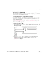
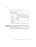
Page 43: ...Ω and 4WΩ This procedure uses a low thermal shorting block across the input connectors 1 Install the shorting block on the front panel voltage input terminals of the DMM as shown below 2 Now Perform the calibration process see Calibration Process on page 39 Enter the calibration value of 0 00 for the calibration value because the source is 0 V SFP Cal step Calibration name Input value VDC 1 Zeros ...

Page 44: ...ue The gain constant is computed from the calibration value entered for the calibration command and from measurements made automatically during the adjustment procedure Most measuring functions and ranges have gain adjustment procedures as shown in the tables below No calibration is required for capacitance as it uses the calibrated current sources in the ohms functions Adjustments for each functi...

Page 45: ... following input values Valid amplitude inputs are within 10 of full scale Valid Frequencies should be within 10 on the value indicated Review Test Considerations on page 16 and Gain Adjustments on page 44 before beginning this procedure Configuration DC and AC Gain 1 Configure each function and range shown in the table below and configure the instrument as shown 2 Apply the input signal shown in ...

Page 46: ...hrough 3 for each gain adjustment point shown in the table above SFP Cal step Step name Calibrator input freq Hz Calibrator input amplitude function 7 DCV Gain 0 2 V 0 2 VDC 8 DCV Gain 2 V 2 VDC 9 DCV Gain 20 V 20 VDC 10 DCV Gain 200 V 200 VDC 11 DCV Gain 300 V 300 VDC 12 ACV Gain 0 2 Vrms 1000 0 2 VAC 13 ACV Gain 2 Vrms 1000 2 VAC 14 ACV Gain 20 Vrms 1000 20 VAC 15 ACV Gain 200 Vrms 1000 200 VAC ...

Page 47: ... ACV Turn ACV fast off by selecting slow filtering using the SFP Perform the following steps using the calibration process described 3 Perform the calibration process in the SFP select the Step set the source enter the Calibrate Value and click Store Calibration Constant Repeat steps 1 through 3 for each gain adjustment point shown in the above table NOTE Before calibrating the flatness on a speci...

Page 48: ... shown in the Input column of the table Enter the actual applied rms input voltage see Adjustments on page 41 3 Perform the calibration process in the SFP select the Step set the source enter the Calibrate Value and click Store Calibration Constant NOTE Before the ACV offset calibration step can be performed on a given range the ACV gain and flatness must be performed first For example you must pe...

Page 49: ...rm the calibration process in the SFP select the Step set the source enter the Calibrate Value and click Store Calibration Constant Repeat steps 1 through 3 for each gain adjustment point shown in the above table NOTE Before step 25 can be performed the 2 VAC gain flatness and zero steps 13 18 and 22 must be performed Review Test Considerations on page 16 and Gain Adjustments on page 44 before beg...

Page 50: ...nd range as shown and configure the instrument as shown below 2 Apply the input signal shown in the Input column of the table Enter the actual applied rms input voltage see Adjustments on page 41 NOTE Steps 27 30 are only available with the M9183A If you are calibrating an M9182A skip these steps Always complete tests in the specified order as shown in the appropriate table Before step 26 can be p...

Page 51: ...ep Step name Calibrator input amplitude function 26 DCI Offset Open 27 DCI Gain 2E 07A 0 0000002 IDC 28 DCI Gain 2E 06A 0 000002 IDC 29 DCI Gain 00002A 0 00002 IDC 30 DCI Gain 0002A 0 0002 IC 31 DCI Gain 002 A 0 002 IDC 32 DCI Gain 02 A 0 02 IDC 33 DCI Gain 2 A 0 2 IDC 34 DCI Gain 2 A 2 IDC NOTE The Fluke 5720A calibrator does not have the capability to source the currents for calibration steps 27...

Page 52: ...ogram the calibrator to DCV value Irange Value of 10 MΩ resistor Example In the value of the resistor is 10 02000e6 then the value programmed for the 20 μA range is 20e 6 10 02000e6 200 4 V For the 2 μA range the value programmed is 2e 6 10 02000e6 20 04 V and for the 200 nA range the value is 200e 9 10 02000e6 2 004 V 3 Perform the calibration process in the SFP select the Step set the source ent...

Page 53: ...lect the Step set the source enter the Calibrate Value and click Store Calibration Constant Repeat steps 1 through 3 for each gain adjustment point shown in the above table Store the new calibration constants see Storing the Calibration Constants on page 41 NOTE Before the ACI Offset on a given range can be performed the ACI gain on that range must be performed for example you must perform step 35...

Page 54: ...cally uses the 4W Ω Gain 20 Ω calibration value when that test step is performed This will not add 1 mΩ to the accuracy If you choose to calibrate step 52 to improve the accuracy the recommendation is to use the Fluke 5720A Use Ext Sense and 2W compensation with stacked BNC connectors at the DUT input to provide a accurate resistance to the DMM NOTE Calibration steps 43 50 51 and 52 are for M9183A...

Page 55: ... flashing in the display b If a problem is encountered the display will flash the message CAL FAILED Check the input value range function and entered adjustment value to correct the problem and repeat the adjustment step 5 Repeat these steps for each gain adjustment point shown in the table 6 Store the new calibration constants see Storing the Calibration Constants on page 41 WARNING Do not use st...

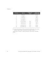
Page 56: ... 43 DCI Source IE 06 A 2W 1 000 000 44 Ohm 4W Gain 20 Ω 4W 19 45 Ohm 4W Gain 200 Ω 4W 190 46 Ohm 4W Gain 2 000 Ω 4W 1 900 47 Ohm 4W Gain 20 000 Ω 4W 19 000 48 Ohm 4W Gain 200 000 Ω 4W 190 000 49 Ohm 4W Gain 2 000 000 Ω 4W 1 900 000 50 Ohm 4W Gain 20 000 000 Ω 4W 19 000 000 51 Ohm 2W Gain 200 000 000 Ω 2W 100 000 000 52 Ohm 2W Gain 20 Ω 2W 19 ...

Page 57: ...mation is subject to change without notice Always refer to the Keysight website for the latest revision Keysight Technologies 2011 2019 Edition 4 May 2019 Printed in Malaysia 5185 9182 5185 9182 www keysight com ...

Reviews: