background image

128

InfiniiMax RC Probe Amplifier and Probe Heads User’s Guide

11

Configuring Infiniium Software for Probe Amplifier and Probe Heads

3

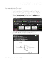
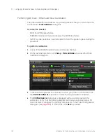
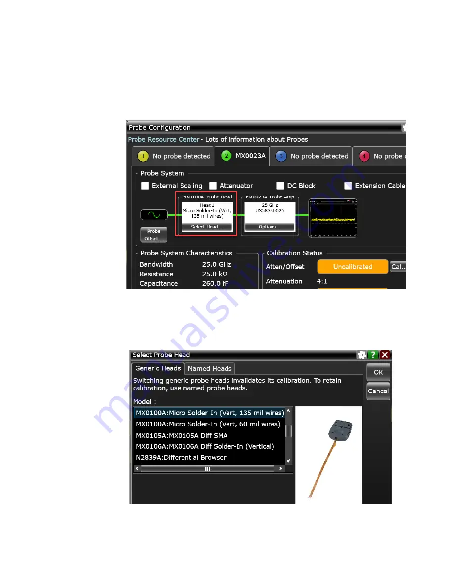
After selecting components, you can select the type of probe head(s) being 

used so that the oscilloscope can apply the appropriate correction filter 


(S parameter) for the probe head(s). Click 

Select Head...

 in the Probe Head block 

of the diagram.

The 

Select Probe Head

 dialog box is displayed in which you can select a generic 

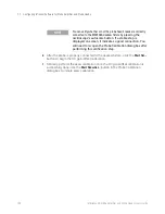
or a named probe head. If you are planning to use more than one type of probe 

head with your amplifier, it is recommended to use Named heads as probe 

calibrations are preserved when you switch Named probe heads.

Summary of Contents for MX0023A InfiniiMax RC

Page 1: ...Keysight MX0023A InfiniiMax RC Probe Amplifier and Probe Heads User s Guide...

Page 2: ...is embodied in its End User License Agreement EULA a copy of which can be found at http www keysight com find sweula The license set forth in the EULA represents the exclusive authority by which the U...

Page 3: ...hed Cable Pair 24 N2812B 1m High Performance Input Cable 24 E2669B Differential Connectivity Kit 25 3 Safety and Regulatory Information Safety Checks and Warnings 28 Instrument Markings and Symbols 30...

Page 4: ...0100A Probe Head 60 MX0100A Probe Head Handling Precautions 60 Replacing the MX0100A Probe Tip Lead Wires 63 Extreme Temperature Testing with the MX0100A Probe Head 66 7 MX0106A InfiniiMax Differentia...

Page 5: ...25B Probe Head with N5426A ZIF Tip Attached 106 SPICE Model of the N5426A ZIF Tip 108 SPICE Deck of N5426A ZIF Tip 109 Using the N5425B Probe Head with N5426A ZIF Tips 111 Using the N5425B Probe Head...

Page 6: ...ystem Responses Typical Corrected System Frequency Response 144 Typical Step Response of Corrected System 145 Typical CMRR 146 14 Returning a Probe Probe Head for Repair Service Contacting Keysight Te...

Page 7: ...7 Keysight InfiniiMax RC Probe Amplifier and Probe Heads User s Guide 1 MX0023A Probe Amplifier Overview Introduction 8 MX0023A Key Features 10 Compatibility with Keysight Oscilloscopes 11...

Page 8: ...be small geometry target devices and extreme environment testing Figure 1 MX0023A Probe Amplifier Table 1 MX0023A Probe Amplifier Components Probe Amplifier Component Description Usage Output Connecto...

Page 9: ...ng near the probe head connector Polarity Markings Polarity markings to indicate the positive and negative inputs of the probe amplifier Probe Head Connector Use this connector to connect your probe a...

Page 10: ...ttenuation Ranges The probe amplifier supports the following two flexible input dynamic ranges 600mVpp 1 1 2 5Vpp 4 1 The input range is automatically configured depending on the vertical scale of the...

Page 11: ...ware Software tab under the Technical Support link Compatible Oscilloscope Adapter Required Required Infiniium Software Version Infiniium Oscilloscopes with AutoProbe II Interface UXR Series 13 33GHz...

Page 12: ...12 InfiniiMax RC Probe Amplifier and Probe Heads User s Guide 1 MX0023A Probe Amplifier Overview...

Page 13: ...InfiniiMax In Line Attenuator Kit 19 N2881A InfiniiMax DC Blocking Capacitors 20 MX0102A Soldering Toolkit 20 N2852A AutoProbe II to AutoProbe III Adapter 23 MX0104A Performance Verification and Desk...

Page 14: ...to Find Detailed Information New InfiniiMax RC Probe Heads supporting higher bandwidths up to 25 GHz Detailed information on each of these probe heads is available as separate chapters in this guide...

Page 15: ...Available Probe Heads and Accessories Overview 2 InfiniiMax RC Probe Amplifier and Probe Heads User s Guide 15 Figure 2 MX0023A Probe Family Diagram...

Page 16: ...signaling standards DDR4 DDR5 LPDDR4 LPDDR5 MIPI D Phy 2 0 3 0 C Phy and M Phy 25 GHz 0 17 pF 0 26 pF 2 MX0106A Differential Solder in Probe Head refer to page 67 for details The most reliable semi p...

Page 17: ...in Probe Head refer to 1168 9B Series Probes user s guide Solder in hands free connection Recommended for DDR4 DDR5 LPDDR4 MIPI D Phy 2 0 12 GHz 0 21 pF 0 35 pF 7 N5380B Differential SMA Probe Head r...

Page 18: ...GHz 0 27 pF 0 44 pF 10 E2678B Differential Socketed Probe Head refer to 1168 9B Series Probes user s guide Measuring signal via a plug on socket connection Removable connection using solder in resist...

Page 19: ...But a few probe heads can be operated over a much larger range of temperatures The N5450B extension cables allow you to physically separate the amplifier from the probe head so that the probe head ca...

Page 20: ...r to the probe amplifier does not matter Refer to the topic Blocking out the DC Component of the Input Signal on page 142 to know more MX0102A Soldering Toolkit The MX0102A soldering toolkit provides...

Page 21: ...ew 2 InfiniiMax RC Probe Amplifier and Probe Heads User s Guide 21 Figure 5 MX0102A soldering toolkit contents Straight Tweezers Cutting Tweezers Double sided Foam Tape Low Temperature Solder Wire Reg...

Page 22: ...460 3121 Double sided Foam Tape To provide strain relief to either the neck portion of the probe head or the plastic housings by taping it to a flat surface such as a tabletop or a DUT circuit board 1...

Page 23: ...our MX0023A probe amplifier Table 6 MX0104A Kit Contents The MX0104A fixture is used with the following two components to promote the proper positioning of the probe during the deskew PV procedure Tab...

Page 24: ...port 2 92 mm male to 2 92 mm male connection Skew error between two cables are matched to within 5 psec and the cable supports up to 40 GHz For detailed specifications of these cables refer to the use...

Page 25: ...E2669B Differential Connectivity Kit The E2669B differential connectivity kit provides multiple quantities of the following three InfiniiMax I probe heads supported for use with the MX0023A probe ampl...

Page 26: ...n both ends 8 01131 85201 25 mil female socket w 20 mil round male pin on other end 8 01131 85202 Heat shrink socket accessory 8 01130 41101 Header adapter 91W 4 01130 63201 82W resistor template 1 01...

Page 27: ...27 Keysight InfiniiMax RC Probe Amplifier and Probe Heads User s Guide 3 Safety and Regulatory Information Safety Checks and Warnings 28 Instrument Markings and Symbols 30...

Page 28: ...ents Do not connect the probe s ground lead to a potential other than earth ground Always make sure the probe and oscilloscope are grounded properly Before making connections to the input leads of thi...

Page 29: ...ould be careful not to damage it through excessive bending or pulling Avoid any mechanical shocks to this product in order to guarantee accurate performance and protection WARNING Whenever it is likel...

Page 30: ...household waste Product Category With reference to the requirement types in the WEEE Directive Annex I this product is classed as a Monitoring and Control Instrumentation product Do not dispose in dom...

Page 31: ...e workstation 32 Probe Amplifier and Probe Heads Handling Precautions 34 Precautions while Connecting and Disconnecting Probe Heads 35 Strain Relieving Techniques for Probe Heads 37 Tips for Soldering...

Page 32: ...station as shown in the following figure Figure 8 Static Safe Workstation Both types of ESD protection illustrated in the above figure when used together provide a significant level of ESD protection...

Page 33: ...RC Probe Amplifier and Probe Heads User s Guide 33 Figure 9 Wrist Strap Connected to Oscilloscope s Ground Socket WARNING These techniques for a static safe workstation should not be used when workin...

Page 34: ...obe end and prevent it from receiving mechanical shock This damage is considered to be abuse and will void the warranty when verified by Keysight Technologies service professionals CAUTION Do not drop...

Page 35: ...lifier from one oscilloscope channel to another Safely Connecting Disconnecting the Probe Amplifier and Probe Head When connecting a probe head to a probe amplifier push the probe head connectors stra...

Page 36: ...Amplifier and Probe Heads For a solder in or a ZIF tip probe head always disconnect the probe head from the amplifier before unsoldering moving to a new position and resoldering the probe head This is...

Page 37: ...f methods that you can use for your probe amplifier probe head Different probe heads can have different cable stiffness Choose a strain relief method appropriate for the cable stiffness Tack Putty rec...

Page 38: ...tack putty to the underside of the probe amplifier body and attach it to a rigid body near your DUT Figure 11 Probe Secured Using Tack Putty You can also use putty with a positioner such as the N2787...

Page 39: ...e Amplifier and Probe Heads User s Guide 39 Velcro Pads The provided Velcro pads can be used to secure your probe amplifier casing to the board Attach Velcro dots to the probe amplifier as well as the...

Page 40: ...Set the temperature of the soldering iron s tip to between 370 C and 420 C for non RoHS standards Use the smallest tip possible Use an optical aid of some sort microscope preferred Employ minimal dwe...

Page 41: ...plifier 2 Disconnect the probe amplifier from the oscilloscope 3 Disconnect the probe head from any circuit under test 4 Gently clean the probe amplifier probe head with a soft cloth dampened with a m...

Page 42: ...42 InfiniiMax RC Probe Amplifier and Probe Heads User s Guide 4 Proper Handling of Probe Amplifier and Probe Heads...

Page 43: ...al Characteristics 48 The tables in this chapter list the specifications and characteristics for the MX0023A probe amplifier and its supported probe heads NOTE All entries included in this chapter are...

Page 44: ...and Specifications MX0023A Probe Amplifier Warranted Specifications Table 9 Warranted Specifications Probe Amplifier Probe Head Specification MX0023A 25 GHz Probe Amplifier MX0100A Micro Probe Head B...

Page 45: ...mmon Mode Range 8 VDC to 100 Hz 0 5 V 100 Hz at 1 1 attenuation 4 V 4 3 V Vcm_term x 0 29 DC to 100 Hz 0 19 V at 1 1 57 attenuation 0 77 Vat 2 57 1 attenuation 100 Hz Maximum Signal Slew Rate 25 V ns...

Page 46: ...ge 30 Vpeak mains isolatedb See maximum input power a Delay can be skewed relative to other signals b Mains isolated is for measurements performed on circuits not directly connected to a mains supply...

Page 47: ...in Probe Head 170 fF 290 fF 23 GHz 18 9 pS 13 4 pS N2839A InfiniiMax II Browser Probe Head 205 fF 340 fF 21 GHz 20 7 pS 14 7 pS MX0105A Differential SMA Probe Head NA 20 GHz 21 8 pS 15 4 pS N5425B Dif...

Page 48: ...C 40 C to 70 C Humidity up to 95 relative humidity non condensing at 40 C up to 90 relative humidity at 65 C Altitude Up to 4 600 meters Up to 15 300 meters Dimensions Refer to the Dimensions section...

Page 49: ...Dimensions 51 MX0100A Input Impedance 53 Setting up and Using the MX0100A Probe Head 56 Trimming the Lead Wires of MX0100A Probe Head 56 Soldering an MX0100A Probe Head to DUT 57 Maintaining the MX01...

Page 50: ...ture range of 55 C to 150 C per JEDEC JESD22 A104 revision E spec making it ideal for environmental chamber testing with the probe head soldered to the DUT inside the chamber This probe head connects...

Page 51: ...e probe amplifier The and indicators on the probe amplifier represent the and inputs on MX0100A probe head When probing single ended signals ensure that the input of the probe amplifier is connected t...

Page 52: ...52 InfiniiMax RC Probe Amplifier and Probe Heads User s Guide 6 MX0100A InfiniiMax Micro Probe Head Figure 17 MX0100A Probe Head Dimensions...

Page 53: ...pedance plot for MX0100A to show the matching of the measured data to the modeled data Matching is generally very good up to the specified bandwidth of the probe head NOTE Input impedance is a functio...

Page 54: ...100A InfiniiMax Micro Probe Head MX0100A SPICE Model The following SPICE model can be used to predict the probe loading effects of the InfiniiMax RC probe and MX0100A probe head combination Figure 18...

Page 55: ...atching subckt MX0100A 1 2 RTipP 1 3 11 58 RTipM 2 4 11 58 C1 3 5 48 86f L1 5 6 24 79n R1 6 4 1 589k Rp1 7 3 88 3 Lp1 8 7 845n Cp1 11 8 223p Rm1 4 9 88 3 Lm1 9 10 845n Cm1 10 11 223p Rp2 11 3 25k Rp3...

Page 56: ...GHz bandwidth Use this lead wire length to accommodate small fine pitch targets The available bandwidth is the full bandwidth of the probe amplifier being used To properly trim the probe head s lead w...

Page 57: ...tip lead wires Always use plenty of flux even if your solder already contains flux This cleans the solder joint and allows for easier flowing solder and quicker dwell times 3 Add solder to existing te...

Page 58: ...02A Soldering Toolkit You can also use putty Velcro or low temperature hot glue instead 6 Connect the soldered MX0100A probe head to the InfiniMax probe amplifier using the supplied MX0103A bullet ada...

Page 59: ...train relief to the probe head and probe amplifier plastic housings by using a double sided foam tape Keysight part number 0460 3122 included in the MX0102A Soldering Toolkit NOTE To view a demo on ho...

Page 60: ...ave connected the MX0100A probe head electrically to a DUT via solder it is best to secure it mechanically as well Always provide strain relief to the probe head setup using putty velcro low temperatu...

Page 61: ...by Using a high quality temperature controlled soldering iron with the tip temperature set as low as possible just high enough to melt the alloy Using a low temperature solder alloy such as SAC Tin Si...

Page 62: ...sistance measurement between the probe head s tip and the center conductor of the SMP connector is 25 2 kohm then the probe head is usable Figure 24 Resistance measurement for an undamaged MX0100A pro...

Page 63: ...n the MX0102A Soldering Toolkit Keep the lead wires solder joints off the raised base to facilitate soldering Cover the entire probe head tip with Kapton tape while ensuring that the lead wires solder...

Page 64: ...e solder in the hole melts down the lead wire will fall into the hole Remove soldering iron as soon as the lead wire falls into the hole 4 Apply flux on the solder joint and then apply a small amount...

Page 65: ...o Probe Head 6 InfiniiMax RC Probe Amplifier and Probe Heads User s Guide 65 5 Cut the extra wire off using a cutting tweezer Keysight part number 8710 2838 included in the MX0102A Soldering Toolkit 6...

Page 66: ...nfiniiMax extreme temperature extension cable To know more about how to use MX0100A in extreme temperatures and the associated cautions refer to Extreme Temperature Probing on page 139 CAUTION Infinii...

Page 67: ...d Accessories 68 MX0106A Dimensions 68 MX0106A Input Impedance 70 Setting up and Using the MX0106A Probe Head 73 Adjusting the Spacing between MX0106A Wires 73 Installing Replacing the MX0106A Probe H...

Page 68: ...ead uses strong 7 mil or optional 4 mil diameter nickel wires that allow solder in connection to very small fine pitch targets The solder in head allows for wide operating temperature of 55 C to 150 C...

Page 69: ...MX0106A InfiniiMax Differential Solder in Probe Head 7 InfiniiMax RC Probe Amplifier and Probe Heads User s Guide 69 Figure 26 MX0106A Probe Head Dimensions...

Page 70: ...an input impedance plot for MX0106A to show the matching of the measured data to the modeled data Matching is generally very good up to the specified bandwidth of the probe head NOTE Input impedance...

Page 71: ...e Amplifier and Probe Heads User s Guide 71 MX0106A SPICE Model The following SPICE model can be used to predict the probe loading effects of the InfiniiMax RC probe and MX0106A probe head combination...

Page 72: ...subckt MX0106A 1 2 RTipP 1 3 42 1877 RTipM 2 4 42 1877 C1 3 5 11 5513f L1 5 6 4 97914n R1 6 4 10 392k Rp1 7 3 93 7363 Lp1 8 7 304785n Cp1 11 8 298 107f Rm1 4 9 93 7363 Lm1 9 10 304785n Cm1 10 11 298 1...

Page 73: ...e MX0106A probe head are replaceable The following two types of wires are available for installation replacement on the MX0106A probe head tip CAUTION Use tweezers to grab and stabilize the lead near...

Page 74: ...TTC 022 600 C or STTC 122 700 C tip soldering iron or equivalent The 600 C tip will help limit burning of the FR4 tip PC board 0 381 mm 0 015 in diameter RMA flux standard tin lead solder wire Fine st...

Page 75: ...the other hand position the end of the wire lead over the solder filled hole Touch the soldering iron to the side of the hole When the solder in the hole melts the wire lead will fall into the hole Re...

Page 76: ...lder in Probe Head Figure 31 Trim Gauge on Probe Head 10 Cut the wires even with the trim gauge on the side opposite to the probe head Figure 32 Cutting Wires Flush with Gauge Each wire lead needs to...

Page 77: ...is connected to the ground of the DUT orient the MX0106A probe head vertically Laying the probe head flat causes coupling to the probe head tip that can degrade the probe performance NOTE The and con...

Page 78: ...form the probe head wires to fit your DUT s geometry 4 Apply flux to the DUT leads and your probe head wires 5 Position the probe head wires on the DUT leads and quickly re flow the solder For additio...

Page 79: ...B InfiniiMax extreme temperature extension cable see page 19 To know more about how to use MX0106A in extreme temperatures and the associated cautions refer to Extreme Temperature Probing on page 139...

Page 80: ...80 InfiniiMax RC Probe Amplifier and Probe Heads User s Guide 7 MX0106A InfiniiMax Differential Solder in Probe Head...

Page 81: ...2839A Browser Probe Head Components 82 N2839A Supplied Accessories 82 N2839A Dimensions 84 N2839A Input Impedance 84 Using the N2839A Browser Probe Head 88 Adjusting Spacing Between the Browser Tips 8...

Page 82: ...head s high bandwidth performance adjustable tips and ergonomic design makes it ideal for hand held measuring of differential and single ended signals See page 43 for characteristics and specification...

Page 83: ...t Spring loaded tips work best when these are either partially or fully compressed and are protected against over compression damage Tweezers 1 ESD safe tweezers to replace tips Refer to the topic Rep...

Page 84: ...ows modeling of the probe loading effects Probe transfer function is generally flat to the specified bandwidth an input impedance plot for N2839A to show the matching of the measured data to the model...

Page 85: ...E Model for the input impedance of the N2839A Browser Probe Head NOTE Refer to the chapter InfiniiMax RC Probe Amplifier and Probe Heads System Responses on page 143 to get a typical corrected frequen...

Page 86: ...kt N2839A 1 2 r1 1 3 41 09 r2 2 4 41 09 c10 3 17 95 34f c11 4 17 95 34f c1 17 5 100f c7 4 9 100f l1 5 6 8 126n l10 9 10 8 126n r3 6 3 139 7 r16 10 17 139 7 csrc1 3 7 35 6f l2 7 8 4 03n r4 8 4 1553 6 c...

Page 87: ...N2839A InfiniiMax II Browser Probe Head 8 InfiniiMax RC Probe Amplifier and Probe Heads User s Guide 87 Figure 36 Input Impedances Zin Modeled and Zin Measured for the N2839A Probe Head...

Page 88: ...acing between the N2839A s tips can be adjusted from 0 mm to 3 mm using the adjustment wheel shown in Figure 37 Figure 37 Adjusting the Tip Spacing Hands Free Probing For hands free stability you can...

Page 89: ...om holder using the mounting dimensions shown in the following figure Use a M2 x 4 mm thread screw to attach the probe head Figure 38 Location and Dimensions of Mounting Hole CAUTION Do not allow the...

Page 90: ...ing the probe head for repair or service you need the serial number of the probe head The N2839A s serial number is located inside the browser s head to amplifier connection as shown in the following...

Page 91: ...ged tips 1 Adjust the browser s tip span adjustment wheel so that the tip span is set to its maximum range 2 To remove an existing tip use your fingers or the supplied ESD safe tweezers Gently pull th...

Page 92: ...41 Inserting a Tip 5 Hold the probe vertically and gently press the tip on a hard surface such as the tweezers to properly seat the tip CAUTION The probe tip arm can be damaged if too much force is ap...

Page 93: ...Probe Amplifier and Probe Heads User s Guide 9 MX0105A InfiniiMax Differential SMA Probe Head Overview 94 MX0105A Probe Head Components 94 MX0105A Dimensions 96 MX0105A SPICE Subcircuit Data 97 MX0105...

Page 94: ...ted The termination network on the probe head can accommodate different standards or needs including supplying a common DC voltage to the termination point See page 43 for characteristics and specific...

Page 95: ...male connection For detailed specifications of these cables refer to the user s guide available in the Document Library tab of www keysight com find N5448B SMA Shorting Adapter The SMA shorting adapt...

Page 96: ...96 InfiniiMax RC Probe Amplifier and Probe Heads User s Guide 9 MX0105A InfiniiMax Differential SMA Probe Head MX0105A Dimensions Figure 43 MX0105A Dimensions All dimensions are in mm inches...

Page 97: ...46 0311 td 15ps t7 7 0 8 0 z0 48 87493 td 15ps t8 8 0 9 0 z0 49 2082 td 15ps t9 9 0 10 0 z0 51 4949 td 15ps t10 10 0 11 0 z0 43 2229 td 15ps t11 11 0 12 0 z0 57 0652 td 15ps t12 12 0 13 0 z0 43 3563...

Page 98: ...be Head MX0105A Input Return Loss S11 Figure 44 MX0105A Input Return Loss S11 NOTE Input return loss is a function of the probe head only The probe amplifier being used does not affect the return loss...

Page 99: ...der the N5426A ZIF Tip to the DUT 112 Using the N5425B Probe Head with N2884A Fine Wire ZIF Tip 116 Step 1 Calibrate the Probe 116 Step 2 Place the N5425B ZIF Probe Head into the Positioner Arm 116 St...

Page 100: ...the ZIF tip s extremely low loading the tips can remain on the DUT as you easily move the probe head from one probing site to the next Figure 45 N5425B Probe Head Attached to a ZIF Tip Soldered to DU...

Page 101: ...micron tungsten wires As wires are extremely small and difficult to see use a high powered microscope when working with these tips 5 fine wire ZIF tips 1 positioner arm with thumb nut to mount the pro...

Page 102: ...x RC Probe Amplifier and Probe Heads User s Guide 10 N5425B InfiniiMax Differential ZIF Probe Head N5425B Probe Head and ZIF Tips Dimensions Figure 46 N5425B ZIF Probe Head Dimensions with N5426A ZIF...

Page 103: ...N5425B InfiniiMax Differential ZIF Probe Head 10 InfiniiMax RC Probe Amplifier and Probe Heads User s Guide 103 Figure 47 N2884A Fine Wire ZIF Tip Dimensions...

Page 104: ...nput impedance plots for N5425B probe head with N5426A and N2884A ZIF tips attached to show the matching of the measured data to the modeled data Matching is generally very good up to the specified ba...

Page 105: ...ifferential probe to probe differential signals Rc or Zc will depend on the DUT circuit vplus connected to DUT plus signal vminus connected to DUT minus signal Input impedance is defined to be vplus v...

Page 106: ...1n Cm2 R1_N Cm2_N 40 93f vsminus vsplus_N vsminus_N AC 1 0 L1 C1_N L1_N 1 356n L2 C2_N L2_N 345 2p Rp1 Lp1_N Rp3_N 38 32 Cm1 R1_N Cm1_N 556 5f Rp2 Lp2_N Rp3_N 30 4 Rp3 Cp1_P Rp3_N 25k Rrtn DUT_Gnd 0 1...

Page 107: ...s User s Guide 107 Figure 49 Measured and Modeled Data Matching for the N5425B Probe Head with N5426A ZIF Tip Attached 10 6 10 7 10 8 10 9 10 10 10 1 10 2 10 3 10 4 10 5 Frequency H z Cse 0 53pF Cdiff...

Page 108: ...RESISTANCE 1u sw tch 100e6 Rsw 2 360p Lom2 163 9 Rom 69f Cp2 23 9 Rp2 3 58n Lp2 3 1n Lp1 38 7 Rp1 180a Cp1 3 1n Lm1 38 7 Rm1 180a Cm1 2 68n L2 2m R2 109 4f C2 98 85 Rtipm 3 14f C1 451 7 R1 98 85 Rtipp...

Page 109: ...1_N Cm2_N 69f vsminus vsplus_N vsminus_N AC 1 0 L1 C1_N L1_N 9 62n L2 C2_N L2_N 2 68n Rp1 Lp1_N Rp3_N 38 7 Cm1 R1_N Cm1_N 180a Rp2 Lp2_N Rp3_N 23 9 Rrtn DUT_Gnd 0 1u Rsw2 vminus 0 1 RESISTANCE 1u swtc...

Page 110: ...uide 10 N5425B InfiniiMax Differential ZIF Probe Head Figure 51 Measured and Modeled Data Matching for the N5426A ZIF Tip Differential Modeled Single Ended Measured Differential Measured Single Ended...

Page 111: ...the tips with flat nose tweezers and bend it back Then bend the tip in the opposite direction and it should break off Figure 52 Breaking Off a ZIF Tip from Packaging Step 2 Attach the N5426A ZIF Tip t...

Page 112: ...lder points with flux The flux core solder does not provide enough flux for this small scale soldering Also put flux on the tips of the leads of the ZIF tip 3 Clean the soldering tip well then add a l...

Page 113: ...s The target could also be via pads or signal traces 1 Add some solder to the target points in the DUT The following figure shows extra solder added to the pads for the first two pins on an IC package...

Page 114: ...e enough solder to form a good fillet and enough flux to make the joint shinny There shouldn t be so much solder that the big solder ball is formed that could cause a solder bridge or overheat the lea...

Page 115: ...N5425B InfiniiMax Differential ZIF Probe Head 10 InfiniiMax RC Probe Amplifier and Probe Heads User s Guide 115 Figure 60 ZIF Tip with ZIF Latch Open...

Page 116: ...an the fine wire ZIF tips since they are very similar in their electrical response characteristics and it is much easier to quickly work with the standard ZIF tip Step 2 Place the N5425B ZIF Probe Hea...

Page 117: ...ntworth 2026 90409 PVX 400 M Manual Linear Manipulator Magnetic Base N2884 64703 Wentworth 5 00 4711 Short Nose Articulated Short Arm Front Figure 62 Micropositioner Step 4 Secure the Micropositioner...

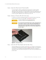
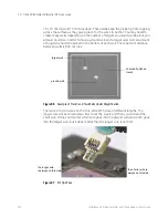
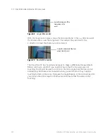
Page 118: ...eezers and lift directly out of the foam See Figure 63 on page 118 Figure 63 Removing the ZIF Tip Step 7 Attach the ZIF Probe Head to the Fine Wire ZIF tip While still grasping the tip with flat nose...

Page 119: ...8 Attach the Fine Wire ZIF tip Onto the Board The procedure described below is for probing the underside of ICs and describes a specific use scenario There may be other possible ways to use this probe...

Page 120: ...f tungsten should be placed in the bottom of each well The maximum distance between wells is 600 microns Figure 66 Example of Trench and Two Wells Under Magnification The two 22 micron wires on the Fi...

Page 121: ...s shown below Figure 68 Wires in Wells How easy the rest of these steps are will depend on how powerful of a microscope you have It may take a while to get adjusted to the process but with some practi...

Page 122: ...Landed The Fine Wire ZIF tip should now be ready to make a differential measurement Before turning on your DUT you need to ensure that the two wires are not touching You should be able to confirm in...

Page 123: ...ectly up The cutouts in the top of the case provide space for these wires when the case is closed However if the tips are not pointing directly up they may miss these cutouts and become damaged CAUTIO...

Page 124: ...short wire that forces their tips to cross the two wires can touch 2 When you set the wires they will buckle The wires may not be touching at their tips in this case so they would look fine under a m...

Page 125: ...x RC Probe 131 Calibration Overview 131 Performing DC Gain Offset and Skew Calibration 132 This chapter provides an overview of the steps you need to perform to configure your MX0023A probe amplifier...

Page 126: ...nection Although the probe amplifier is auto detected the probe head or other components such as attenuators DC blocking capacitors or extension cables that you use in the probing setup are not automa...

Page 127: ...tem section 2 Select the checkbox displayed with the component s that you have used in the probing setup The selected component s then get added to the probe connection diagram Figure 73 Example of DC...

Page 128: ...loscope can apply the appropriate correction filter S parameter for the probe head s Click Select Head in the Probe Head block of the diagram The Select Probe Head dialog box is displayed in which you...

Page 129: ...to ensure that you get the maximum performance and dynamic range from your InfiniiMax RC probe By applying an offset most or all of the DC component can be subtracted and the signal can be positioned...

Page 130: ...fset Offset is applied at the probe The vertical offset control on the oscilloscope s front panel controls the probe offset Used for measuring differential signals Used for measuring single ended sign...

Page 131: ...ng the probe Allow the probe to warm up for 15 minutes before starting the calibration procedure Remove any attenuator attached to the probe You cannot calibrate your probe with the attenuators attach...

Page 132: ...be in place during the procedure To perform calibration 1 Connect the MX0023A probe to an oscilloscope channel 2 On the oscilloscope menu click Setup Probe Calibration to access the Probe Calibration...

Page 133: ...e MX0104A deskew fixture a Connect the 50 terminator to the MX0104A fixture This terminator is provided with the fixture b Connect the MX0104A fixture to the Cal Out connector on the oscilloscope c Tu...

Page 134: ...A 3D Probe Positioner to hold the probe in place and to maintain a steady contact of probe tips with the deskew fixture f While pressing down on the MX0104A fixture s spring loaded clamps insert the p...

Page 135: ...135 spring loaded clamps ground plane and center conductor signal path are labeled in the following figure The clamping of the probe head to the deskew fixture is shown below CAUTION Do not press down...

Page 136: ...alibration once the DC gain offset calibration is successfully done Use the Start Skew Cal button in the Probe Calibration dialog box to initiate skew calibration NOTE You can verify whether or not th...

Page 137: ...fier and Probe Heads User s Guide 12 Making Measurements Probing Single ended Signals using a Differential Probe Head 138 Extreme Temperature Probing 139 Probing Ungrounded Devices 141 Blocking out th...

Page 138: ...of the probe to bring a signal within the probe s dynamic range For a differential signal the offset is applied at the oscilloscope channel This method of applying probe offset allows the full benefi...

Page 139: ...reme temperature testing may undergo discoloration texture changes when used under high temperatures However such changes do not affect the probe head s performance or measurement quality Table 21 Pro...

Page 140: ...moisture accumulating in the form of condensation on the probe components as well as the DUT If this occurs wait until the moisture has evaporated before making any measurements CAUTION Additional car...

Page 141: ...f ungrounded devices such as a battery powered device where the DUT is not grounded to the oscilloscope via the AC mains ground you can establish the ground connection in the following two ways Connec...

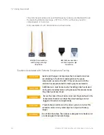
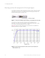
Page 142: ...d Figure 77 Placement of DC Blocking Capacitor Between a Probe Amplifier and a Probe Head You can also use these DC blocking capacitor with the N2880A In Line Attenuators The order of the two products...

Page 143: ...is connected to an oscilloscope channel and the proper probe head is selected the oscilloscope calculates a DSP correction filter that includes the probe head probe amplifier and oscilloscope channel...

Page 144: ...onse Figure 79 shows the frequency response of an ideal 25GHz brickwall filter and the typical DSP corrected probe response filtered by the brickwall filter Figure 79 Typical Corrected Frequency Respo...

Page 145: ...nses for the following two responses an ideal 25GHz system response and the typical DSP corrected probe response The configuration used is the MX0100A probe head with the 25 GHz MX0023A probe amplifie...

Page 146: ...1 shows the typical CMRR applicable to all probe heads described in this guide for the MX0023A probe amplifier except the MX0105A SMA probe head The CMRR for the MX0105A probe head is shown in Figure...

Page 147: ...nfiniiMax RC Probe Amplifier and Probe Heads System Responses 13 InfiniiMax RC Probe Amplifier and Probe Heads User s Guide 147 Figure 82 CMRR of MX0105A Probe Head With MX0023A 25 GHz Probe Amplifier...

Page 148: ...148 InfiniiMax RC Probe Amplifier and Probe Heads User s Guide 13 InfiniiMax RC Probe Amplifier and Probe Heads System Responses...

Page 149: ...office for any additional details 2 Write the following information on a tag and attach it to the malfunctioning equipment Name and address of owner Product model number for example MX0023A Product S...

Page 150: ...ILE If any correspondence is required refer to the product by serial number and model number Contacting Keysight Technologies for Technical Assistance For technical assistance contact your local Keysi...

Page 151: ...nt Parts 152 MX0100A Probe Head MX0106A Probe Head Table 22 MX0100A Replacement Parts Description Qty Order Part Number Probe Tip Wire 004 diameter To make ground connections 1 wire spool MX0102 21301...

Page 152: ...ther Replacement Parts Description Vendor Part Number Qty Probe Amplifier Ground Wire 01131 21301 1 160 damped wire accessory 01130 21303 34 each Keysight E5381 82103 1 Coupling tag for N5450B extreme...

Page 153: ...cilloscopes 11 Infiniium software 125 Infiniium software version 11 in line attenuators 142 input impedance N2839A 87 input range 10 isolation 32 L long wire ZIF tip 101 low temperature hot glue 38 M...

Page 154: ...s 94 SMA shorting adapter 95 soldering toolkit 20 soldering ZIF tip 112 spacing between wires 73 s parameters 10 143 SPICE model N2839A 85 spring loaded tips 83 standard ZIF Tip 101 static safe access...

Reviews: