58
InfiniiMax RC Probe Amplifier and Probe Heads User’s Guide
6
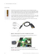
MX0100A InfiniiMax Micro Probe Head
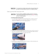
4
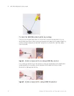
Connect the MX0100A probe head’s lead wires to DUT by positioning these
wires on DUT and then reflowing joint while heating momentarily. .
5
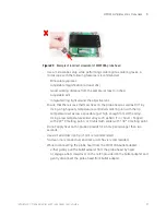
Provide strain-relief to the probe head by taping its mid portion to a flat surface
such as a tabletop using the double-sided foam tape (such as Keysight part
number 0460-3122 included in the MX0102A
Soldering Toolkit). You can also
use putty, Velcro or low temperature hot glue instead.
6
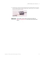
Connect the soldered MX0100A probe head to the InfiniMax probe amplifier
using the supplied MX0103A bullet adapter.
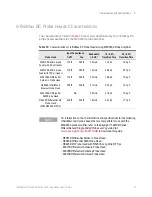
NOTE
Keep the temperature as low as possible while still reflowing the solder at
the joint of concern. The following are some of the useful tips to maintain
low temperature during soldering.
- A temperature-controlled soldering iron is the best way to do this. Set it
for no more than 350
o
C if using standard lead-free solders and 150
o
C for
tin-bismuth solder.
- Do not rest a soldering iron on a probe joint for more than a few seconds.


