background image

General Information

1

N7010A User’s Guide

19

Contacting Keysight Technologies

For technical assistance, contact your local Keysight Call Center.
• In the Americas, call 1 (800) 829-4444
• In other regions, visit http://www.keysight.com/find/assist
• Before returning an instrument for service, you must first call the Call Center at 

1 (800) 829-4444.

Summary of Contents for N7010A

Page 1: ...Keysight N7010A Active Termination Adapter User s Guide...

Page 2: ...U S government customers under its standard commercial license which is embodied in its End User License Agreement EULA a copy of which can be found at http www key sight com find sweula The license s...

Page 3: ...fety Information 14 Inspecting the N7010A 17 Cleaning the N7010A 17 Returning the Product for Service 18 Contacting Keysight Technologies 19 2 Specifications and Characteristics 21 Specifications and...

Page 4: ...4 N7010A User s Guide Contents...

Page 5: ...is a 30 GHz single ended adapter featuring a user adjustable common termination voltage Vterm and extremely low noise performance The N7010A is ideal for high SNR low noise measurements for standards...

Page 6: ...ut can be damaged by mating to low quality SMA connectors You can also connect SMP cables using an adapter not provided The relatively inexpensive connector saver protects the N7010A s 2 9 mm connecto...

Page 7: ...er connections to the 2 9 mm precision RF input connector Always properly align any mating connection before tightening the connection to the specified torque CAUTION Torque all cables and adapter con...

Page 8: ...llow the 50 ohm input of the N7010A to be terminated to a voltage rather than to ground which is required by some devices under tests DUTs Vterm can be set anywhere from 4V to 4V however Vin must neve...

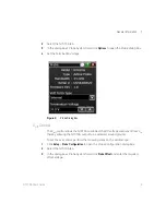
Page 9: ...ol The Voff control allows the N7010A to subtract the DC voltage component from Vin thereby allowing the N7010A output to be centered around ground To set the Voff control perform the following steps...

Page 10: ...of Vin which means the signal into the oscilloscope is centered around ground 600 mV Vinput Vtermination 600 mV NOTE Vin is the voltage at the input of the N7010A If the source driving the N7010A has...

Page 11: ...Gear 3 data rate signal at 5 8304 Gb s The amplitude swing is 140 mVpp Figure 4 shows the signal connected directly to the Infiniium oscilloscope s channel input without using a N7010A Figure 5 shows...

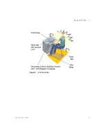
Page 12: ...ed alone To ensure user safety the static safe accessories must provide at least 1 M of isolation from ground Purchase acceptable ESD accessories from your local supplier CAUTION When the N7010A is co...

Page 13: ...General Information 1 N7010A User s Guide 13 Figure 6 ESD Workstation...

Page 14: ...revent fire or damage to this product or products connected to it review and comply with the following safety precautions Be aware that if you use this probe assembly in a manner not specified the pro...

Page 15: ...ice personne WARNING Whenever it is likely that the ground protection is impaired you must make the instrument inoperative and secure it against any unintended operation WARNING If you energize the in...

Page 16: ...voltage and specified type normal blow time delay etc should be used Do not use repaired fuses or short circuited fuse holders To do so could cause a shock or fire hazard WARNING Capacitors inside the...

Page 17: ...ion tests notify your Keysight Technologies Sales Office If the shipping container is damaged or the cushioning materials show signs of stress notify the carrier as well as your Keysight Technologies...

Page 18: ...functioning equipment Name and address of owner Product model number for example N7010A Product Serial Number for example USXXXXXXXX Figure 7 Location of Serial Number Description of failure or servic...

Page 19: ...echnologies For technical assistance contact your local Keysight Call Center In the Americas call 1 800 829 4444 In other regions visit http www keysight com find assist Before returning an instrument...

Page 20: ...20 N7010A User s Guide 1 General Information...

Page 21: ...this chapter list the specifications and characteristics for the N7010A adapter Bandwidth and input resistance at DC are warranted specifications for the N7010A Connect the N7010A to a powered on osci...

Page 22: ...Vterm range 4V to 4V Vterm accuracy 2 mV Voffset range 4V to 4V Input signal range 0 6V Vin Vterm 0 6V Input resistance at DC 50W 3 Maximum non destructive input voltage 8V DC to 50 kHz 5Vrms above 50...

Page 23: ...or the product s toxic substances for the China RoHS requirements The CE mark is a registered trademark of the European Community ISM GRP 1 A denotes the instrument is an Industrial Scientific and Med...

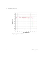
Page 24: ...24 N7010A User s Guide 2 Specifications and Characteristics Figure 8 Typical N7010A Bandwidth...

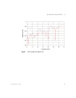
Page 25: ...Specifications and Characteristics 2 N7010A User s Guide 25 Figure 9 N7010A Typical Input Return Loss...

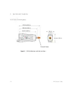
Page 26: ...26 N7010A User s Guide 2 Specifications and Characteristics N7010A Dimensions Figure 10 N7010A Dimensions with Connector Saver...

Page 27: ...destroy high performance probes resulting in costly repairs Always wear a wrist strap when handling probe components and ensure that cables are discharged before being connected CAUTION Ensure that th...

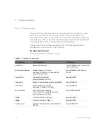
Page 28: ...est Equipment Critical Specification Model Number Oscilloscope Supported Oscilloscope Infiniium 90000Q series V series and Z series oscilloscopes Microwave CW Generator Maximum Frequency 32 GHz Power...

Page 29: ...e power meter s Power Ref connector and calibrate the meter 4 Set up the power meter to display measurements in units of Watts 5 Connect the test setup as shown in Figure 11 Do not use any additional...

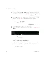
Page 30: ...ngs Channel 1 ON Channels 2 3 4 OFF Vertical scale Channel 1 50 mV div Horizontal scale 16 ns div display 8 cycles of a 50 MHz waveform Figure 12 Oscilloscope horizontal scale entry 7 Select Setup Acq...

Page 31: ...measurement to Vrms using the following expression For example if the power meter reading is 4 0 W then Vin 4 0 x 10 6 X 50 1 2 14 1 mVrms 13 Record the Vin value here and in Table 7 on page 37 as Vi...

Page 32: ...expression Record this value here and in Table 7 on page 37 as the Calculated Gain at 50 MHz Gain at 50 MHz ______________ 16 Change the microwave generator s frequency to 30 GHz 17 Change the oscillo...

Page 33: ...ximum frequency using the following expression The gain at 50 MHz was calculated in step 15 and recorded in Table 7 on page 37 as the Calculated Gain at 50 MHz For example if Vout 30 GHz 13 825 mV Vin...

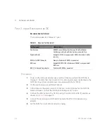
Page 34: ...ation Voltage is set to zero 4 Connect the BNC cable to the N7010A using the SMA m to BNC f adapter as shown in Figure 15 on page 35 5 Connect the remaining end of the BNC cable to the BNC f to banana...

Page 35: ...d input resistance Input resistance Ra ______________ 8 Reverse the banana plug connection to the DVM Record the measured input resistance Input resistance Rb ______________ 9 Calculate the average in...

Page 36: ...36 N7010A User s Guide 3 Performance Verification The average input resistance must meet the 50 ohm 3 specification 48 5 Average Input Resistance 51 5...

Page 37: ...y Recommended Next Test Date Table 7 Results for Test 1 Bandwidth Test Frequency Vin Read on Power Meter Vout Read on Oscilloscope Calculated Gain Test Limit 3 dB 50 MHz 30 GHz Table 8 Results for Tes...

Page 38: ...38 N7010A User s Guide 3 Performance Verification...

Page 39: ...7 inspecting 17 K Keysight Technologies contacting 19 L low frequency input maximum 8 M maximum AC voltage 10 maximum input voltage 5 measurement category 23 N N7010A cable care 5 dimensions 26 graph...

Page 40: ...40 N7010A User s Guide Index...

Reviews: