U3042AE16
Troubleshooting the Test Set
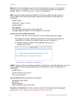
d. If the DC Indicator LEDs are not on, suspect the main power supply module or front panel
switch. The power supply (0950-4729) terminal connections should also be verified with a
DVM. Verify the voltages on the power supply label.
e. If rear panel fan is not operating and the DC Indicator LEDs are
on
; replace fan.
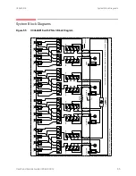
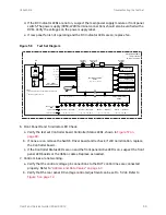
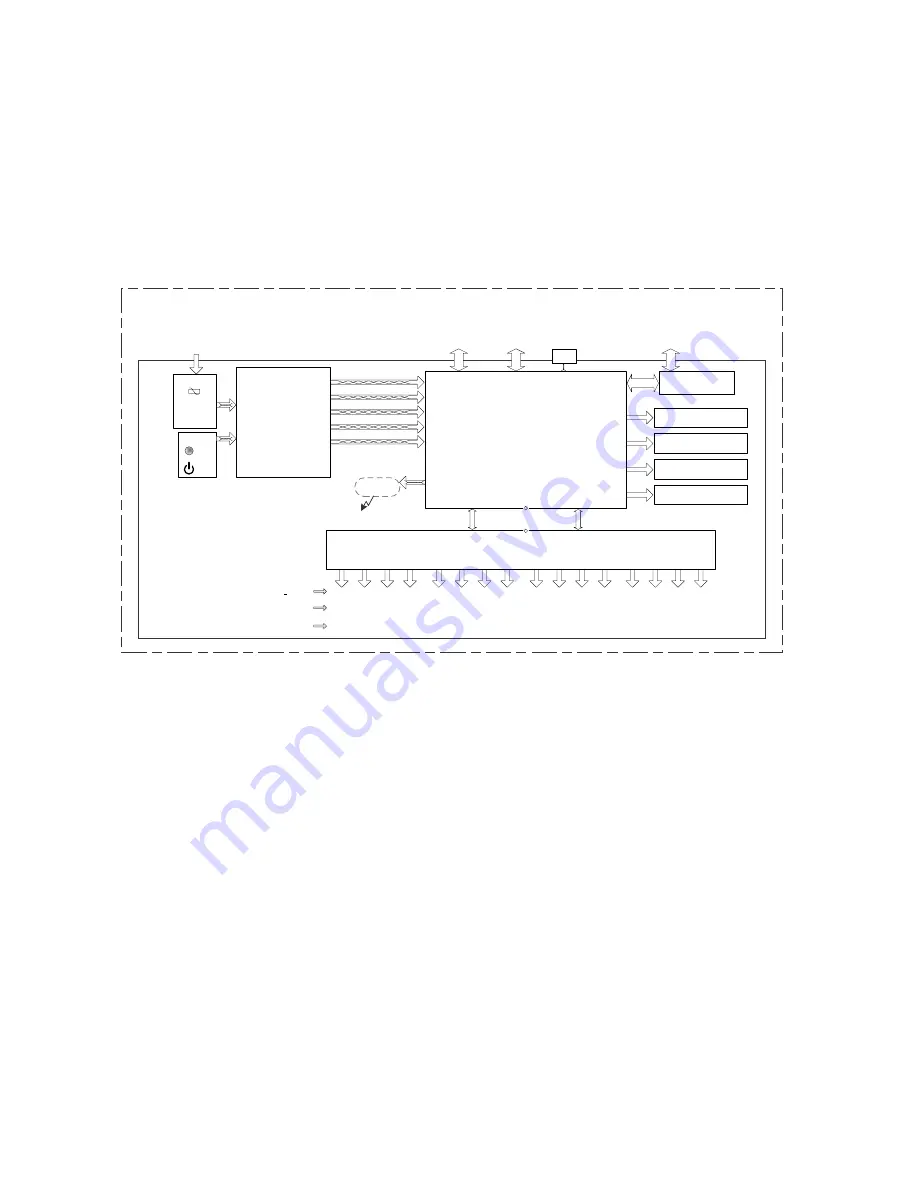
Figure 5
8
Test Set Diagram
6.
Front Panel R and S indicator LED Check.
a.
Verify the test set Controller board Controller Status LEDs, shown in
.
b.
If none are on remove the Switch Driver board and recheck, if still no indication, replace
the Controller board.
c.
If the Controller Status LEDs are
on
and the front panel Active LED is
on
, suspect the front
panel LED boards or the ribbon cables. Replace as needed.
7.
Control Lines are not working.
a.
Verify that the control voltage pin connections to the DUT control lines are connected
properly. Refer to
“Address and Data Values” on page 4
.
b.
Verify that the rear panel DC voltage control adjustment can be set to 5 Vdc. Refer to
.
PS1 650W
DC Power Supply
Test Set Control Bd.
PCB 1
12 / 15 Vdc
S1
-12 / -15 Vdc
+24 Vdc
3 / 5 Vdc
Switch Interface Bd.
PCB2
Test Set
Interface
Pass Thru
Interface
J1
J4
J2
J3
J9
Ext. DUT
Control
J11
J12
J14
J13
AC Line
Filter Assy
FS2
–
FS3
AC
IN
J12
S2
S3
J38
J39
P1
Active ON
LED (Frt.Pnl)
J16
J5
FAN
J15
Std.By
FS1
AC IN
*
**
PCB7
Ports 8,12,16, 20 LED (Frt.Pnl)
J6
J7
J8
PCB6
Ports 7, 11, 15, 19 LED (Frt.Pnl)
PCB5
Ports 6, 10, 14, 18 LED (Frt.Pnl)
PCB4
Ports 5, 9,13, 17 LED (Frt.Pnl)
S4
S5
S6
S8
J10
J20
J18
J28
J26
J34
Front Panel
Active
9 / -10 Vdc
Signal Path Name
Test Set Port Group
Ext Control Bd.
PCB3
(5, 15, -15vdc)
(3, 5, -12, 15, -15 Vdc)
-12 Vdc
(5 Vdc)
(5, 15, -15 Vdc)
NOTES:
*
The
DC
voltages
shown,
are
functionally
used
by
this
part.
**
On
board
programmed
Device.
*
**
*
*
*
*
(5 Vdc)
*
(5 Vdc)
*
(5 Vdc)
*
(5 Vdc)
S7
J36
Source ---- Receiver
--- 5 - 9 - 13 - 17 ---
RF Switch (+ 15 Vdc)
JTAG
J5
Keysight U3042AE16
16-Port Test Set
10 MHz
–
26.5 GHz
*
J10
S9
J13
S10
S11
S12
S13
S14
S16
J7
J21
J19
J29
J27
J35
S15
J37
Source ---- Receiver
--- 6 - 10 - 14 - 18 ---
Source ---- Receiver
--- 7 - 11 - 15 - 19 ---
Source ---- Receiver
--- 8 - 12 - 16 - 20 ---
User's and Service Guide U3042-90012
69

