2
Operation and Features
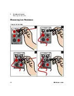
Measuring Low-Resistance
44
U3606B User’s Guide
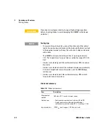
Low-resistance measurement summary
C A U T I O N
Disconnect circuit power and discharge all high-voltage capacitors
before measuring resistance or conductance, or testing circuit
continuity, to avoid damaging the U3606B or the device under test.
N O T E
DC power supply functions are locked
The DC power supply functions are locked when you select the
low-resistance (Lo
Ω
) measurements. You cannot use the DC power
supply module simultaneously with the digital multimeter module when
you are measuring 4-wire low-resistance measurements.
To unlock the DC power supply functions, exit the low-resistance (Lo
Ω
)
measurement by selecting another multimeter measurement.
N O T E
Delayed response for low-resistance readings
For measuring low-resistance, a delayed response should be expected
from the front panel display. For remote interface operation, increase the
SCPI query time-out value (typically 15000 ms).
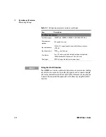
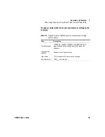
Table 2-5
Low-resistance measurement summary
Item
Description
Available ranges
100 m
Ω
, 1000 m
Ω
, 10
Ω
, 100
Ω
, 1000
Ω
Measurement
method
Four-wire, the test current is sent from the FORCE
terminals and the resistance is measured by the SENSE
terminals.
Input protection
•
FORCE terminals: Protected with a 3.15 A/250 V FF fuse
•
SENSE terminals: 1000 V
rms
on all ranges, < 0.3 A short
circuit
Summary of Contents for U3606B
Page 1: ...Keysight U3606B Multimeter DC Power Supply User s Guide ...
Page 2: ...THIS PAGE HAS BEEN INTENTIONALLY LEFT BLANK ...
Page 3: ...U3606B User s Guide I ...
Page 16: ...XIV U3606B User s Guide THIS PAGE HAS BEEN INTENTIONALLY LEFT BLANK ...
Page 25: ...Introduction 1 Preparing the U3606B U3606B User s Guide 7 Adjust the carry handle 1 2a 3 2b ...
Page 27: ...Introduction 1 Preparing the U3606B U3606B User s Guide 9 Figure 1 3 Rack mount dimensions ...
Page 120: ...3 DC Power Supply Operation Square Wave Operation 102 U3606B User s Guide Enable the output 7 ...


