102
3
、
Lead the wire according to the hole marked “1” in Figure 3.2.57, and connect the wire to the Aruino
expansion board with reference to Figure 2.3.58. After the completion, as shown as Figure 2.3.57.
Figure 3.2.57 Wire Connection Diagram
F
igure 3.2.58 Connection of Arduino and Receiving Head Wires
4
、
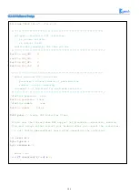
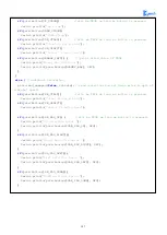
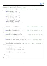
Open Lesson\ModuleDemo\PS2X\PS2X.ino on the CD
Finally, download the program to the Arduino development board and turn on the PS2 remote control. If the
receiver head is connected to the remote controller (or the pairing is successful), the indicator light on the
Summary of Contents for Hummer-Bot-1.0
Page 1: ...Hummer Bot 1 0 Instruction Manual V 2 0 ...
Page 18: ...15 Step4 You need to install motors Figure 3 1 5 Schematic diagram of motor installation ...
Page 50: ...47 Figure 3 2 15 Diagram of Data without Obstacles ...
Page 83: ...80 Test code Path hummer bot Lesson ModuleDemo IrkeyPressed IrkeyPressed ino ...


