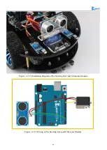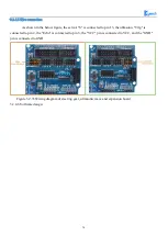
67
receiving time interval of the ultrasonic, which can be recorded with the time counter, and don't forget to
divided it with 2.
The ultrasonic is a sound wave which will be influenced by temperature. If the temperature changes
little, it can be approximately considered that the ultrasonic velocity is almost unchanged in the transmission
process. If the required accuracy of measurement is very high, the measurement results should be to
corrected with the temperature compensation. Once the velocity is determined, the distance can be obtained.
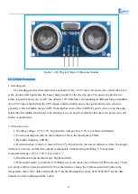
This is the basic principle of ultrasonic distance measurement module which is shown in Fig.3.2.29:
Figure .3.2.29 the Principle of Ultrasonic Distance Measurement Module
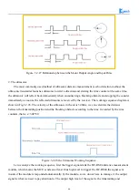
The ultrasonic is mainly divided into two parts, one is the transmitting circuit and the other is the
receiving circuit, as shown in Fig.3.2.30. The transmitting circuit is mainly composed of by the inverter
74LS04 and ultrasonic transducer T40, the first 40kHz square wave from the Arduino port is transmitted
through the reverser to the one electrode on the ultrasonic transducer, the second wave is transmitted to
another electrode on ultrasonic transducer, this will enhance the ultrasonic emission intensity. The output
end adopts two parallel inverters in order to improve the driving ability. the resistance R1 and R2 on the one
hand can improve the drive ability of the 74LS04 outputting high level, on the other hand, it can increase the
damping effect of the ultrasonic transducer and shorten the free oscillation time.
The receiving circuit is composed of the ultrasonic sensor, two-stage amplifier circuit and a PLL circuit.
The reflected signal received by the ultrasonic sensor is very weak, which can be and amplified by the
two-stage amplifier. PLL circuit will send the interrupt request to the microcontroller when receiving the
signal with required frequency. The center frequency of internal VCO in the PLL LM567 is
, the locking bandwidth is associated with C3. Because the transmitted ultrasonic
frequency is 40kHz, the center frequency of the PLL is 40kHz, which only respond to the frequency of the
signal, so that the interference of other frequency signals can be avoided.
The ultrasonic sensor will send the received the signal to the two-stage amplifier, the amplified signal
will be sent into the PLL for demodulation, if the frequency is 40kHz, then the 8 pins will send low level
interrupt request signal to the microcontroller P3.3, the Arduino will stop the time counter when detecting
low level.
)
2
1
1
.
1
/(
1
0
C
R
f
P
=
Summary of Contents for Hummer-Bot-1.0
Page 1: ...Hummer Bot 1 0 Instruction Manual V 2 0 ...
Page 18: ...15 Step4 You need to install motors Figure 3 1 5 Schematic diagram of motor installation ...
Page 50: ...47 Figure 3 2 15 Diagram of Data without Obstacles ...
Page 83: ...80 Test code Path hummer bot Lesson ModuleDemo IrkeyPressed IrkeyPressed ino ...


