45
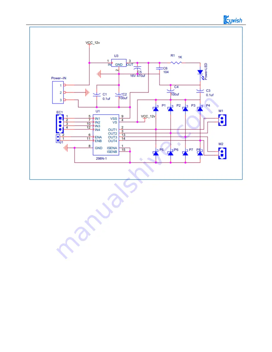
Fig.3.2.4 Schematic Diagram of Motor Drive
Four DC motors with high power L298N drive enable "Hummer-Bot" to run faster than conventional
two-wheel car, the acceleration time is shorter and the structure is more stable. However, in the actual
application, we need to adjust the speed of the car because of environmental or other factors, yet this does not
affect the forward, backward, stop, flexible steering of the car, so we use PWM to control the speed of the
motor(Note: PWM is a way to simulate the simulation output via square waves with different duty cycles.),
Arduino PWM port outputs a series of square waves with fixed frequency, the power and current of the motor
can be amplified after receiving the signal, thereby changing the motor’s speed. The speed coordination of
two motors on the right and left wheels can achieve the forward, backward, turning and other functions of the
car. Figure 2.4.5 shows the sequence diagram of PWM duty cycles.
Summary of Contents for Hummer-Bot
Page 1: ...Hummer Bot Instruction Manual Github https github com keywish keywish hummer bot...
Page 7: ...4...
Page 8: ...5...
Page 9: ...6...
Page 10: ...7...
Page 13: ...10 Fig 2 2 Several commonly usedArduino...
Page 15: ...12 After the completion as shown...
Page 16: ...13 The second step is to Welding wire on the motor...
Page 17: ...14 After the completion as shown...
Page 19: ...16 Fig 3 1 3 Diagram of Aluminum Alloy Bracket Installation...
Page 20: ...17 Fig 3 1 4 Diagram of Motor Installation Fig 3 1 5 Fixing Screw for Motor...
Page 24: ...21 Fig 3 1 10 Diagram of Wheel Installation Fig 3 1 10 Diagram of Wheel Screw Fixation...
Page 29: ...26 Fig 3 1 15 Diagram of Tracing Module Installation...
Page 30: ...27 Fig 3 1 16 Diagram of Screw Brackets Fig 3 1 17 The Back of Complete Installation...
Page 32: ...29 First install the screws on the UNO After the completion as shown...
Page 43: ...40 Fig 3 1 33 Diagram of Wires Arrangement Fig3 1 34 the Effect of Whole Assembly...
Page 56: ...53 Fig 3 2 11 Diagram of Data with Obstacles Fig 3 2 12 Diagram of Data without Obstacles...
Page 69: ...66 Fig 3 2 22 Diagram of Steering Gear Fig 3 2 23 Composition of Steering Gear...
Page 93: ...90 Fig 3 2 42 Receiving Head Position Fig 2 3 43 Installation of Receiving Head...


