70
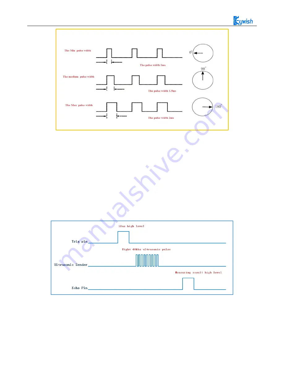
Fig.3.2.27 Relationship between the Motor Output Angle and Input Pulse
2. The ultrasonic
The most commonly used method of ultrasonic distance measurement is echo detection method, the
ultrasonic transmitter launches ultrasonic toward a direction and starting the time counter at the same time,
the ultrasonic will reflect back immediately when encountering a blocking obstacle, and stopping the
counter immediately as soon as the reflected ultrasonic is received by the receiver. The working sequence
diagram is shown in Fig.3.2.28. The velocity of the ultrasonic in the air is 340m/s, we can calculate the
distance between the transmitting position and the blocking obstacle according to the time t recorded by the
time counters, that is: s=340*t/2.
Fig.3.2.28 the Ultrasonic Working Sequence
Let us analyze the working sequence, first the trigger signal starts the HC-RS04 distance measurement
module, which means the MCU sends an at least 10us high level to trigger the HC-RS04,the signal sent
inside of the module is responded automatically by the module, so we do not have to manage it, the output
signal is what we need to pay attention to. The output high level of the signal is the transmitting and
Summary of Contents for Hummer-Bot
Page 1: ...Hummer Bot Instruction Manual Github https github com keywish keywish hummer bot...
Page 7: ...4...
Page 8: ...5...
Page 9: ...6...
Page 10: ...7...
Page 13: ...10 Fig 2 2 Several commonly usedArduino...
Page 15: ...12 After the completion as shown...
Page 16: ...13 The second step is to Welding wire on the motor...
Page 17: ...14 After the completion as shown...
Page 19: ...16 Fig 3 1 3 Diagram of Aluminum Alloy Bracket Installation...
Page 20: ...17 Fig 3 1 4 Diagram of Motor Installation Fig 3 1 5 Fixing Screw for Motor...
Page 24: ...21 Fig 3 1 10 Diagram of Wheel Installation Fig 3 1 10 Diagram of Wheel Screw Fixation...
Page 29: ...26 Fig 3 1 15 Diagram of Tracing Module Installation...
Page 30: ...27 Fig 3 1 16 Diagram of Screw Brackets Fig 3 1 17 The Back of Complete Installation...
Page 32: ...29 First install the screws on the UNO After the completion as shown...
Page 43: ...40 Fig 3 1 33 Diagram of Wires Arrangement Fig3 1 34 the Effect of Whole Assembly...
Page 56: ...53 Fig 3 2 11 Diagram of Data with Obstacles Fig 3 2 12 Diagram of Data without Obstacles...
Page 69: ...66 Fig 3 2 22 Diagram of Steering Gear Fig 3 2 23 Composition of Steering Gear...
Page 93: ...90 Fig 3 2 42 Receiving Head Position Fig 2 3 43 Installation of Receiving Head...


