82
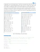
3, Copying the following program to IDE (you can also directly open the matching program in the CD), and
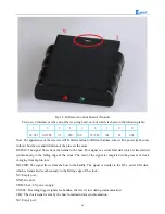
downloading to the development board, pulled out the transparent plastic sheet marked as "1" in the
Fig.3.2.33. Then opening the serial port monitor, observing and recording the values on it while pressing
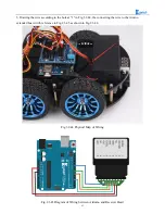
keys on the remote control towards the receiving head as shown in Fig.3.2.37.
#include <IRremote.h>
int
RECV_PIN
=
12
;
// Define the IR receiver pin to be 12
IRrecv irrecv
(
RECV_PIN
);
decode_results results
;
void
setup
()
{
Serial
.
begin
(
9600
);
irrecv
.
enableIRIn
();
// Initialize the infrared receiver
}
void
loop
()
{
if
(
irrecv
.
decode
(&
results
))
{
Serial
.
println
(
results
.
value
,
HEX
);
// Output the receive code in hexadecimal
Serial
.
println
();
// Add a blank line for easy viewing of the output
irrecv
.
resume
();
// Receive the next value
}
}
Fig.3.2.37 Remote Encoding Query
Summary of Contents for Hummer-Bot
Page 1: ...Hummer Bot Instruction Manual Github https github com keywish keywish hummer bot...
Page 7: ...4...
Page 8: ...5...
Page 9: ...6...
Page 10: ...7...
Page 13: ...10 Fig 2 2 Several commonly usedArduino...
Page 15: ...12 After the completion as shown...
Page 16: ...13 The second step is to Welding wire on the motor...
Page 17: ...14 After the completion as shown...
Page 19: ...16 Fig 3 1 3 Diagram of Aluminum Alloy Bracket Installation...
Page 20: ...17 Fig 3 1 4 Diagram of Motor Installation Fig 3 1 5 Fixing Screw for Motor...
Page 24: ...21 Fig 3 1 10 Diagram of Wheel Installation Fig 3 1 10 Diagram of Wheel Screw Fixation...
Page 29: ...26 Fig 3 1 15 Diagram of Tracing Module Installation...
Page 30: ...27 Fig 3 1 16 Diagram of Screw Brackets Fig 3 1 17 The Back of Complete Installation...
Page 32: ...29 First install the screws on the UNO After the completion as shown...
Page 43: ...40 Fig 3 1 33 Diagram of Wires Arrangement Fig3 1 34 the Effect of Whole Assembly...
Page 56: ...53 Fig 3 2 11 Diagram of Data with Obstacles Fig 3 2 12 Diagram of Data without Obstacles...
Page 69: ...66 Fig 3 2 22 Diagram of Steering Gear Fig 3 2 23 Composition of Steering Gear...
Page 93: ...90 Fig 3 2 42 Receiving Head Position Fig 2 3 43 Installation of Receiving Head...


