5
The gas supply line must be ¾” or larger. If flexible or semi-rigid connections are used, the inside diameter must
be the equivalent of ¾” iron pip e or larger. All connections of the flexible and semi-rigid type must comply with
all local and national requirements. Make sure gas piping is clean and free of dirt, piping compound, and
obstructions.
WARNING:
PRIOR TO LIGHTING, CHECK ALL JOINTS IN THE GAS SUPPLY LINE FOR LEAKS. USE SOAP AND WATER
SOLUTION. DO NOT USE AN OPEN FLAME.
After piping has been checked for leaks, all piping receiving gas should be fully purged to remove air.
GAS PRESSURE REGULATOR INSTALLATION
Gas regulator pressure is preset at 5” Water Column (W .C.) for natural gas, and 10” W .C.
For propane gas. Minor adjustments may be required based on site specific gas pressure.
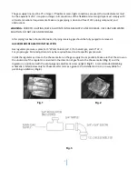
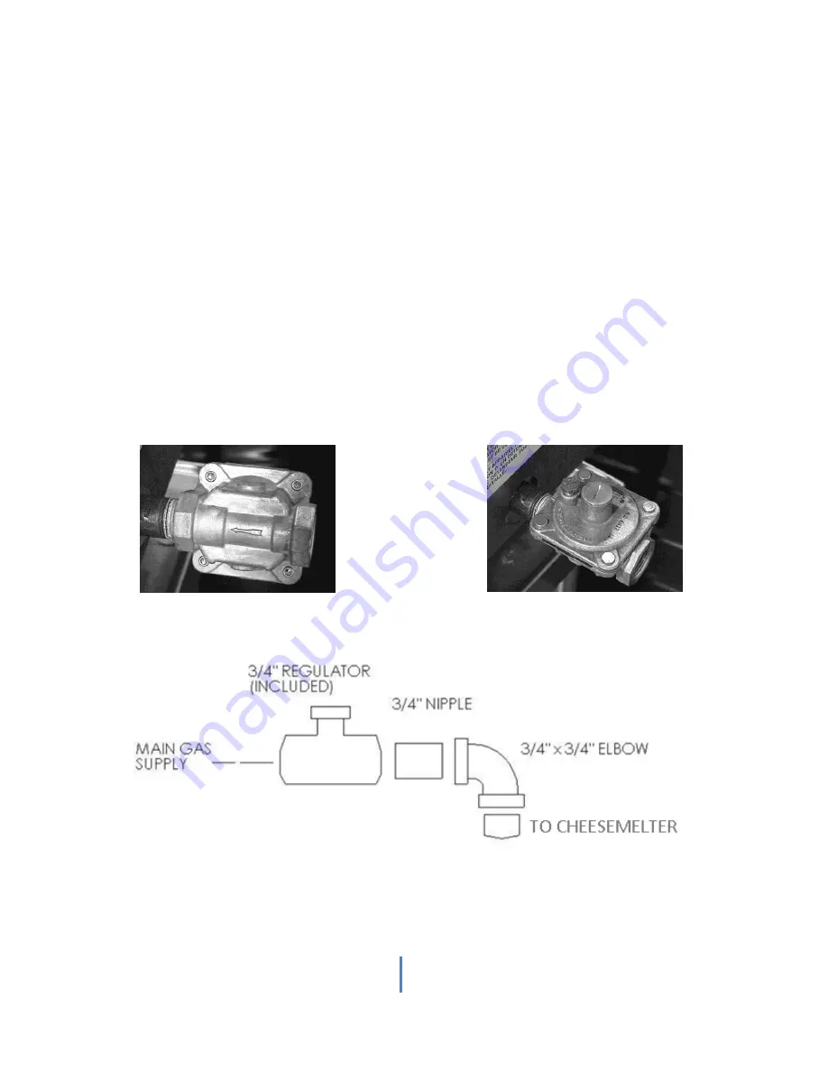
Install the regulator as close to the Cheese melter on the gas supply line as possible. Make sure that the arrow on
the underside of the regulator is oriented in the direction of gas flow to the Cheese melter (
Fig. 1
) and the
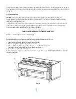
regulator is positioned with the vent plug and adjustment screw upright (
Fig. 2
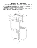
). A recommended plumbing
schematic is listed below only for Cheese melter units as a guide to the installer and it is in no way liable for
plumbing installation (
Fig. 3
).
Fig.1
Fig.2
Fig.3


