7
MODEL #A3000 – 3,000LB (1361KG) WINCH
ASSEMBLy
22. Connect the battery leads from the contactor to the
vehicle’s battery (black to black, and red to red, see
diagram on page 8).
23. Check for proper drum rotation. Turn the clutch
cap to the RELEASE position. Pull out some cable
from the drum and then turn the clutch cap to the
ENGAGE position to engage the gears. Make sure
your vehicle is running and press the cable out
button on the switch. If the spool is turning and
releasing more cable, then your connections are
accurate. If the spool is turning and collecting more
cable, then reverse the leads on the motor. Repeat
and check rotation.
Wiring the Winch
15. Connect the yellow and blue wires to the motor
terminals on the winch. Torque the nuts on the
motor to 5.7 N-m (50 in lbs) Route the opposite
ends to the contactor location. (See diagram on
page 8).
16. Connect the yellow and blue wires to the contactor
block (yellow to yellow, blue to blue). DO NOT
tighten nuts. (See diagram page 8).
17. Connect the red and black wires to your contactor
block (red to red, black to black). DO NOT tighten
nuts. Route the opposite ends to the battery
location (See diagram page 8).
18. Connect the mini rocker switch to the contactor
block (black to black, green to green). (See diagram
on page 9).
19. Once all wiring is connected to the contactor, finish
mounting it to the contactor location using supplied
M6 hardware (See diagram page 8).
20. Torque the contactor terminal nuts to 4.5 N-m
(40 in lbs) Do NOT over tighten.
21. Place all terminal boots over terminals and secure
all cables with zip ties or electrical tape.
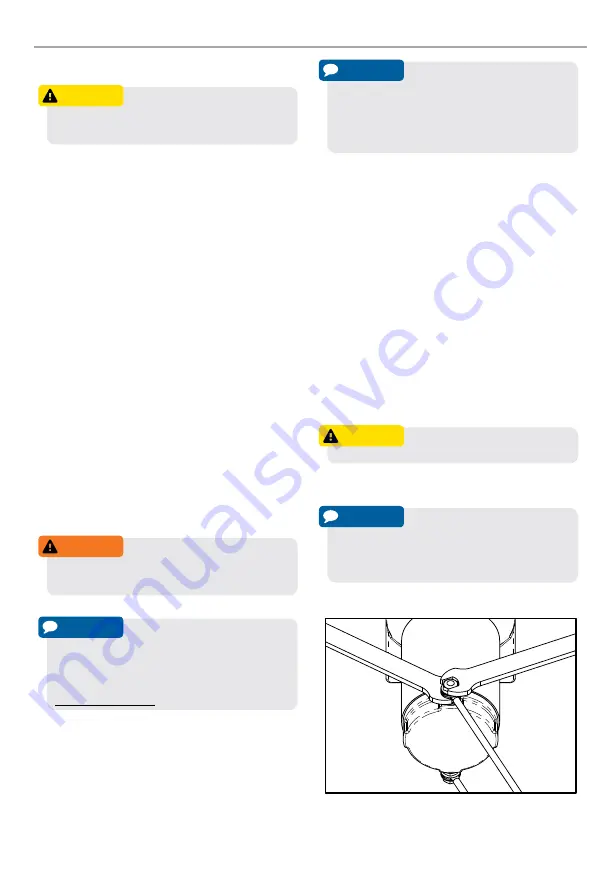
Proper Terminal Tightening
CauTIon
Never route electrical wires across
any sharp edges, through or near moving parts, or
near parts that become hot.
WarnInG
Failure to follow specific wiring
instructions may result in damage to your wiring
system or equipment.
noTICe
Depending on the location of the
contactor, you may need to use an alternate winch
wiring configuration. Please see the “Alternate
Winch Wiring Diagram” available on:
www.kfiproducts.com
noTICe
If you are installing the hand
remote along with the mini rocker switch, you will
need to connect the remote socket to the contactor
and then the mini rocker switch to the remote
socket (see diagram on page 9).
CauTIon
Battery cables should not be drawn
taut. Leave some slack for cable movement.
noTICe
Always hold the bottom nut with
a wrench while tightening motor wire terminals.
Do not allow the bottom nut to spin, else you may
damage the end cap.


