background image

6

AS-50x

Mounting bolts must be SAE grade 5 or better 

and torque to 17 ft. lbs.

Before you start to install this winch, 

disconnect the vehicle ground and positive 

leads from the battery.

This KFI 5,000 lb winch is designed with a bolt 

pattern that is standard in this class of winch. 

Many winch mounting kits are available that 

utilize this bolt pattern for the most popular 

ATV’s and UTV’s. You can find most of the 

ATV/UTV winch mounts on our Website 

www.kfiproducts.com

1.  Install the winch and fairlead with the  

supplied hardware per the instructions 

provided with the model specific mounting 

kit or prepare a flat, secure mounting 

location for the winch. 

Step 2-Mount the Contactor

1.  Find  a  location  for  the  contactor.    If  the 

Model specific mounting kit does not indicate 

a  recommended  contactor  location,  then 

it  is  recommended  that  the  contactor  be 

mounted close to the battery in a clean dry 

location.  Make sure the location you chose 

allows  sufficient  clearance  from  all  metal 

components.  Drill mounting holes if required.  

Once location is found do not install until all 

wiring is completed.

Step 3-

UTV Dash Mounted

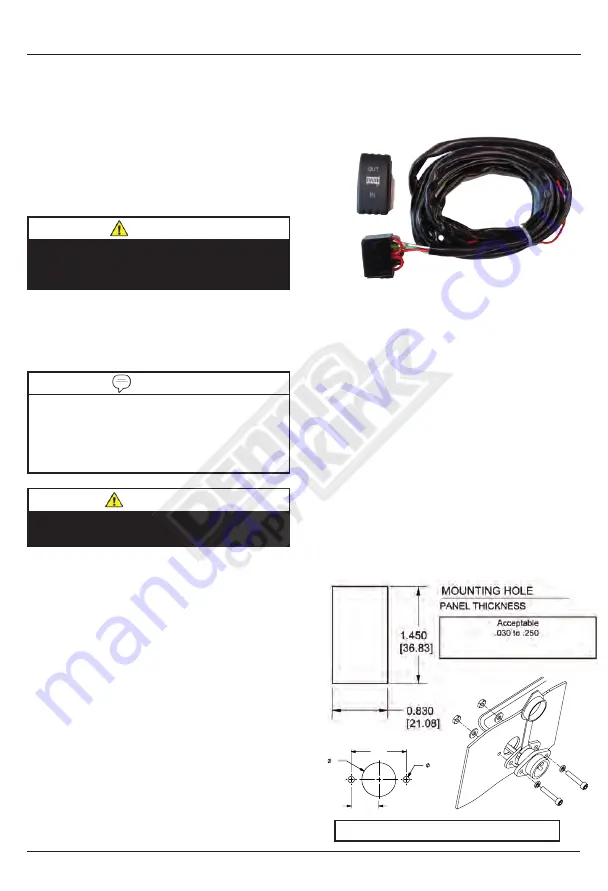
Rocker Switch Kit

1.  Most UTV’s and SxS’s have predefined 

switch locations that are pre-scribed or 

marked for mounting and require finish cut 

with a knife.

2.  Use the cut-out dimensions shown below 

to cut-out the switch location If your dash 

doesn’t have the pre-scribed areas

3.  Once your switch is mounted you can route 

the wires back to where your contactor is 

located.

4.  Splice the end of the red wire to an ignition 

(keyed) controlled power source using the 

supplied wire splice.  You may need to use a 

test light to locate a suitable wire.  The wire 

should only have power when the key is in 

the ON position.

Step 1-Mount the Winch

Installation

CAUTION

WARNING

2.  Attach the winch using the M8 x 25 or 30 

bolts and washers through the fairlead 

bracket or model specific mount and then 

into the winch. 

3.  Disengage  the  clutch  by  rotating  the  clutch 

cap  to  the  “RELEASE”  position.  Release 

the synthetic rope and pull through the roller 

fairlead.

4.  Attach the clevis hook and hand strap to the 

cable.

NOTE

If you chose not to use a model specific 

mounting kit, you will need to drill holes in the 

structural support of the vehicle.  Be certain 

that your structural support will stand up to the 

pulling forces of this winch.

Installation

1"

3/16"

1 5/8"

13/16"

Not to scale. Do NOT use as a template

Summary of Contents for Assault AS-50x

Page 1: ...nd pictures are not easy to see At times you will find the overall look of the instructions to be less than professional However we feel it is better to provide what we have rather than provide nothin...

Page 2: ...Model AS 50x Owner s Manual and Operating Instructions 5000 lb ATV UTV WINCH Revision Date 2020 12 09...

Page 3: ...Tips for Safe Operation 10 Self Recovery 10 Winching Techniques 11 Maintenance 12 Lubrication 12 Cable Assembly Replacement 12 AS 50x Specifications 13 Performance Specifications 13 Model Winch Diagra...

Page 4: ...out our products visit our web site at www kfiproducts com Record the model as well as date and place of purchase for future reference Have this information available when ordering parts and when maki...

Page 5: ...DANGER indicates an imminently hazardous situation which if not avoided will result in death or serious injury Manual Conventions This manual uses the following symbols to help differentiate between d...

Page 6: ...RNING Never step over a cable or near a cable under load WARNING The cable may break before the motor stalls For heavy loads at or near rated capacity use a pulley block snatch block to reduce the loa...

Page 7: ...ct the remote control and finish spooling by rotating the drum by hand with the clutch disengaged Keep hands clear of the fairlead and drum while the winch is under power WARNING Duration of winching...

Page 8: ...the winch mount or bumper Free spooling Clutch 5 The clutch allows the operator to manually disengage RELEASE the spooling drum from the gear train Engaging the clutch ENGAGE locks the winch into the...

Page 9: ...3 UTV Dash Mounted Rocker Switch Kit 1 Most UTV s and SxS s have predefined switch locations that are pre scribed or marked for mounting and require finish cut with a knife 2 Use the cut out dimension...

Page 10: ...nd black to black Do NOT tighten nuts Route the other ends to your battery location See diagram on page 8 4 Connect the Dash rocker switch to the contactor black to black and green to green See diagra...

Page 11: ...t 1 877 346 2050 for instructions or visit our website at www kfiproducts com and look in the support section BATTERY BLUE YELLOW RED BLACK NEG POS NEG POS TO WINCH YELLOW POST TO BATTERY BLACK POST T...

Page 12: ...sting against your fairlead Tighten fasteners 3 To stow hook engage clutch and retract synthetic rope onto winch spool until hook is snug against the hook stopper and Switch Wiring Diagram Installatio...

Page 13: ...h the engine off the battery may be drained and too weak to restart the engine Get to know your winch before you actually need to use it We recommend that you set up a few test runs to familiarize you...

Page 14: ...eing winched can be slowly driven to add assistance to the winching process Avoid shock loads keep the cable under tension 15 The vehicle to be winched should be placed in neutral and the parking brak...

Page 15: ...on may be required using a high temperature lithium grease Cable Assembly Replacement It is recommended that any modifications be performed by a manufacturer s authorized repair facility and that only...

Page 16: ...es 113 mm Length 13 9 inches 353 mm Bolt Pattern 4 7 8 x 3 124mm x 76 mm Line Speed and Motor Current First Layer Line Pull Max lbs 0 1500 2500 3500 4500 5000 kgs 0 680 1134 1588 2041 2268 Line Speed...

Page 17: ...14 AS 50x AS 50x Specifications Parts Diagram...

Page 18: ...5 x 8 1 32 500200 Drum Assembly 1 33 500012 Hexagon Shaft 1 34 450002 Spring Coupling 1 35 400015 B Winch Wires Black 2 36 400016 B Battery Wires Black 2 37 250062 Wire Tap 2 38 250061 Terminal Protec...

Page 19: ...r without normal power Worn Brushes Get a replacement End Cap A CAPKIT Call KFI Technical support Loose or corroded cable connections Clean Tighten or Replace Motor is overheating Winch running time i...

Page 20: ...aused by compression from the cable being wound on the winch drum or through a pulley block This is usually considered normal A sign of heat damage is when you compress D the glazed section E of the c...

Page 21: ...roducts P O Box 32 721 Sata Drive Spring Valley MN 55975 www kfiproducts com Made in China 2019 Kappers Fabricating Inc Corporate Office Kappers Fabricating Inc P O Box 32 1015 Industrial Drive Spring...

Reviews: