background image

15

ASP-35

ASP-35 Specifications

Winch Parts List

No Part#

Description

Qty

01

MOTOR-AS35

Motor Assembly

1

02

410018-B

Bolt M5 x 16

2

03

450001

Coupling, I

1

04

450003A

Coupling, II

1

05

410001

Spring

1

06

500001

Self-Seal Packing

2

07

500018

Tie Bar Φ10

2

08

500002A

Clutch Cover

1

09

410005

Gear Ring I 

1

10

AS350001

Gear Carrier Assembly, 

Output

1

11

410009

Gear Carrier Assembly, 

Input

1

12

GB2760BB0606-

2RS

Radial Ball Bearing 606 

Sealed

1

13

500003

O-Ring Φ19 x 2.4

1

14

410014

Clutch Spring

1

15

GB2760BB6802-

2RS

Radial Ball Bearing 

6802  Sealed

1

16

500004

Clutch Cap

1

17

450030-B

Cap Screw M6 x 16

1

18

250017-B

Washer Φ6, Locking

1

19

250011

Circlip Φ15

1

20

500005

Bolt M4 x 20

1

21

500006

Washer Φ4, Flat

2

22

500007A

Gear Housing

1

23

500008

Cam Clutch Gear

1

24

500009

Axis Support Bushing

1

25

410015

Sun Gear, Input

1

26

AS250002

Gear Carrier Assembly

1

27

410007A

Gear Ring II

1

28

410004A

O-Ring Φ100 x 1.9

1

29

410016

Drum Bushing

2

30

500010A

Hexagon Tie Bar 6 x 87mm

1

31

500011

Hexagon Socket Set 

Screw M5 x 8

1

32

AS350100

Drum Assembly

1

33

500012

Hexagon Shaft

1

34

450002

Spring, Coupling

1

35

AP-BAT-WIRE1

Battery Wire with Loom 

Covering - Red

1

No Part#

Description

Qty

36

AP-BAT-WIRE2

Battery Wire - Black

1

37

AP-WIN-WIRE

Winch Wires - Blue/Yellow

2

38

AP-MR

Mini Rocker Switch

1

39

250047-BF

MR Mounting Angle

1

40

250054-B

Washer #6, Locking 

2

41

250053-B

Screw #6-32 x 9/32 in.

2

42

250052-B

Nut M5

2

43

250045-BF

Handlebar Switch 

Clamp

2

44

250050-B

Washer Φ5, Locking 

2

45

250049-B

Washer Φ5, Flat

2

46

250051-B

Screw M5 x 18

3

47

AM250003

Hexagonal Socket 

Button Head Screw 

M8 x 25

4

48

250063-B

Washer Φ8, Locking

4

49

250070-B

Washer Φ8, Flat

8

50

AM250004

Carriage Bolt M10 x 25

2

51

NV-740

Sportsman Winch 

Mount - Wrinkle Texture

1

52

SE-RF

Roller Fairlead, POM 

Rollers

1

53

250036-B

Locking Nut M10

2

54

AP-CONT

Contactor(11D2)

1

55

SYN19-S50

Synthetic Cable, 3/16 

in. x 50 ft

1

56

SE-HOOK

Clevis Hook - Black 

E-Coat

1

57

250030-B

Strap - Black

1

58

250032-B

Bolt M8 x 25

4

59

ATV-SCHS

Split Cable Hook Stop-

per 

1

60

AM250005

Hexagonal Flange 

Self-Threading Screw 

M5 x 25

2

61

250061

Terminal Protector

6

62

AS-CAPKIT

End Cap Assembly

1

63

450026-B

Bolt M4 x 25

1

64

500016

Square Nut

4

65

500017

Elastic Cylindrical Pin 

Φ3 x 14

4

66

250048-B

Screw M5 x 25

1

Summary of Contents for Assault ASP-35

Page 1: ...Model ASP 35 Owner s Manual and Operating Instructions 3500 lb ATV UTV WINCH Revision Date 2019 04 01 ...

Page 2: ......

Page 3: ...niques 11 Maintenance 12 Motor 12 Lubrication 12 Cable Assembly Replacement 12 ASP 35 Specifications 13 Performance Specifications 13 Model Winch Diagram 14 Winch Parts List 15 Troubleshooting 16 Plowing Alert 16 Warranty 17 Warranty Qualifications 17 Repair Replacement Warranty 17 Do not return the unit to the place of purchase 17 Warranty Exclusions 17 Normal Wear 17 Installation Use and Mainten...

Page 4: ......

Page 5: ...bout our products visit our web site at www kfiproducts com Record the model as well as date and place of purchase for future reference Have this information available when ordering parts and when making technical or warranty inquiries This Booklet Every effort has been made to ensure the accuracy and completeness of the information in this manual We reserve the right to change alter and or improv...

Page 6: ... DANGER indicates an imminently hazardous situation which if not avoided will result in death or serious injury Manual Conventions This manual uses the following symbols to help differentiate between different kinds of information The safety symbol is used with a key word to alert you to potential hazards in operating and owning a winch Follow all safety messages to avoid or reduce the risk of ser...

Page 7: ...WARNING Never step over a cable or near a cable under load WARNING The cable may break before the motor stalls For heavy loads at or near rated capacity use a pulley block snatch block to reduce the load on the wire rope WARNING Do not use the winch to secure or hold a vehicle for a long period of time Do not use the winch to secure a vehicle for transport WARNING Disconnect the remote control and...

Page 8: ...ect the remote control and finish spooling by rotating the drum by hand with the clutch disengaged Keep hands clear of the fairlead and drum while the winch is under power WARNING Duration of winching pulls should be kept as short as possible If the motor becomes uncomfortably hot to the touch stop winching immediately and let it cool down for a few minutes Do not pull for more than one minute at ...

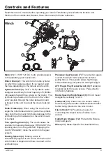
Page 9: ...he synthetic rope from abrasion on the winch mount or bumper Free spooling Clutch 5 The clutch allows the operator to manually disengage RELEASE the spooling drum from the gear train Engaging the clutch ENGAGE locks the winch into the gear system Braking System 6 Braking action is automatically applied to the winch drum when the winch motor is stopped and there is a load on the synthetic rope Plan...

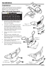
Page 10: ...brush guards 4 Remove the lower cowling B on the Sportsman models and the bumper C and front assembly clip D on the Scramblers as shown in Figure 2 5 5 Remove and discard the Winch pocket cover E shown in Figure 2 5 6 Remove the winch assembly from the box and cut the zip tie that is holding the power wires for packaging Step 1 ATV Install Preparation Installation Before you start to install this ...

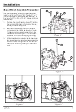
Page 11: ...s sembly as shown in Figure 6 2 Move the contactor G to the new location on the side of the mount as shown in Figure 7 Make sure the contactor plug H is in the orientation shown in Figure 7 To mount the contactor re use the self tapping screws F 3 While mounting the contactor to the new loca tion you will want to route the wires around the winch as shown in Figure 8 9 You should not have to loosen...

Page 12: ...r chase of this additional wire harness Polaris Part 4015094 Please refer to application chart for details 6 Cut the zip tie holding the wire to the frame and remove the protective cap 7 Route the wire over to the contactor location on the winch assembly and connect it to the other 2 pin connector K that is coming out of the contactor shown in Figure 11 8 Secure this wire if needed with zip ties N...

Page 13: ...d attach the switch plug O to the integrated plug M and install a new zip tie at location L L N O M Step 5 Reinstall 1 Turn your ATV ignition on and test the winch operation 2 On the EXT 450 and 570 re assemble the center cover A from step 1 2 and close the front rack 3 On the 850 and 1000 models re assemble the front rack 4 On all models re install the front lower cover front clip on the scramble...

Page 14: ...ith the engine off the battery may be drained and too weak to restart the engine Get to know your winch before you actually need to use it We recommend that you set up a few test runs to familiarize yourself with rigging techniques the sounds your winch makes under various loads the way the cable spools on the drum etc Inspect the cable and equipment before each use A frayed or damaged rope should...

Page 15: ...being winched can be slowly driven to add assistance to the winching process Avoid shock loads keep the cable under tension 15 The vehicle to be winched should be placed in neutral and the parking brake released Only release the loads to the winch This can damage the winch cable and vehicle 16 The winch is meant for intermittent use Under full load with a single line rig do not power in for more t...

Page 16: ...ion may be required using a high temperature lithium grease Cable Assembly Replacement It is recommended that any modifications be performed by a manufacturer s authorized repair facility and that only manufacturer supplied parts be used 1 Rotate the clutch cap to the Release position 2 Extend Cable Assembly to its full length Note how the existing cable is connected to the inside of the drum 3 Re...

Page 17: ...mm Width 4 44 inches 113 mm Length 13 62 inches 346 mm Bolt Pattern 4 7 8 x 3 124mm x 76 mm Line Speed and Motor Current First Layer Line Pull Max lbs 0 1000 2000 2500 3500 kgs 0 454 907 1134 1589 Line Speed 12 VDC FPM 12 1 10 8 8 2 7 5 4 9 MPM 3 7 3 3 2 5 2 3 1 5 Max Current amps 28 60 90 115 180 Cooling Time minutes 5 5 5 5 5 Line Pull and Cable Capacity Layers of cable on drum 1 2 3 4 5 Max pul...

Page 18: ...14 ASP 35 ASP 35 Specifications Model Winch Diagram ...

Page 19: ...0100 Drum Assembly 1 33 500012 Hexagon Shaft 1 34 450002 Spring Coupling 1 35 AP BAT WIRE1 Battery Wire with Loom Covering Red 1 No Part Description Qty 36 AP BAT WIRE2 Battery Wire Black 1 37 AP WIN WIRE Winch Wires Blue Yellow 2 38 AP MR Mini Rocker Switch 1 39 250047 BF MR Mounting Angle 1 40 250054 B Washer 6 Locking 2 41 250053 B Screw 6 32 x 9 32 in 2 42 250052 B Nut M5 2 43 250045 BF Handle...

Page 20: ...or without normal power Worn Brushes Get a replacement End Cap A CAPKIT Call KFI Technical support Loose or corroded cable connections Clean Tighten or Replace Motor is overheating Winch running time is too long Allow winch to cool down periodically WARNING PLOWING ALERT READ BEFORE USING YOUR WINCH TO LIFT A PLOW ATV winches are one of the most widely used methods of lifting a plow When used prop...

Page 21: ...his warranty will not apply to parts and or labor if this winch is deemed to have been misused neglected involved in an accident abused loaded beyond the winch s limits modified installed improperly or wired incorrectly to any electri cal component Normal maintenance is not covered by this warranty Other Exclusions The winch cable or synthetic rope Cosmetic defects such as paint decals etc Accesso...

Page 22: ...ns including the wearing of appropriate protective gear and clothing and operating the product safely and under safe conditions Purchaser fully accepts and assumes responsibility for all such risks losses costs and damages incurred as a result of the use of the product whether by purchaser or anyone using the product with or without purchaser s permission Your purchase of the product shall constit...

Page 23: ...aused by compression from the cable being wound on the winch drum or through a pulley block This is usually considered normal A sign of heat damage is when you compress D the glazed section E of the cable and it remains hardened In this case the cable must be replaced Prolonging the life of your synthetic cable Exercising proper care to prolonging the life of your cable is your responsibility 1 Mi...

Page 24: ...Products P O Box 32 721 Sata Drive Spring Valley MN 55975 www kfiproducts com Made in China 2018 Kappers Fabricating Inc Corporate Office Kappers Fabricating Inc P O Box 32 1015 Industrial Drive Spring Valley MN 55975 USA ...

Reviews: