background image

Page 4

Installation Instructions

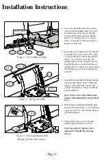
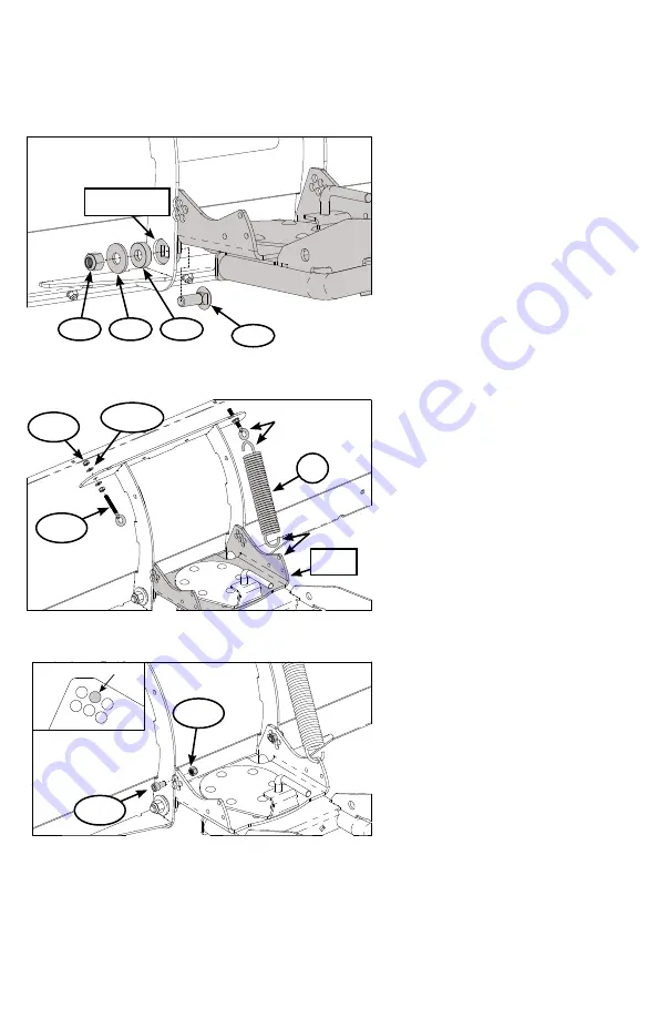
1.  To secure the blade to the tube system, 

place the pitch bushing (Item 7.4.1) into 
the blade gusset hole. Secure the tube 
system and the blade together with the 
Items 7.3.4 carriage bolt, 7.3.3 washer 
and 7.3.2 lock nut, as shown in Figure 1. 
Repeat on other side.

2.  Insert the plow springs (Item 7.2) into the 

top smaller rear holes in the UTV cradle, 
as shown in Figure 2. Place the eyebolts 
(Item 7.3.8) onto the end of the plow 
springs and secure the eyebolts onto the 
plow blade gusset, as shown in Figure 2 
using Items 7.3.9 and 7.3.10. Leave spring 
tension loose as you will decide tension 
in Step 5.

3.  Assemble on machine and decide desired 

pitch of blade. (Blade pitch controls the 
angle of which the blade contacts the 
ground.) Each hole is 5 degrees of blade 
pitch adjustment.


Note: Figure 3 shows the default pitch 
position. Recommended for proper blade 
level

.

4.  With springs installed pitch blade under 

tension and install Items 7.3.5 socket head 
cap screw and 7.3.1 lock nut into desired 
pitch position hole

5.  Tighten nuts down on eye bolt until 

desired spring tension is reached. 


Note: For each 1/4” that the nut is 
tightened it will add 8 lbs of spring 
tension. 

“Figure 1” Pivot Bolt Assembly

BLADE GUSSET 

HOLE

7.3.4

7.4.1

7.3.3

7.3.2

“Figure 3” Pitch Adjustment Bolt

(Spring not shown for clarity.)

DEFAULT LOCATION

7.3.1

7.3.5

“Figure 2” Spring Assembly

UTV 

CRADLE

7.2

7.3.8

7.3.9

7.3.10

Summary of Contents for OPEN TRAIL 105635

Page 1: ...Instruction Manual UTV Plow Tube System Rev H 10 13 2021 ...

Page 2: ...d result in death or serious injury CAUTION CAUTION indicates a potentially hazardous situation which if not avoided may result in minor or moderate injury CAUTION CAUTION used without the safety alert symbol indicates a potentially hazardous situation which if not avoided may result in property damage NOTE If you have questions regarding your plow we can help Please call our help line at 1 800 99...

Page 3: ... fast could cause damage to winch if applicable or plow Never raise the plow above point of contact as it could cause damage to machine or winch if applicable Always perform regular inspections and maintenance on plow tubes and hardware before use Operate with extreme caution on slopes steep grades and rough terrain Be aware of any possible hidden objects under the snow Do not ram the blade into t...

Page 4: ...decide tension in Step 5 3 Assemble on machine and decide desired pitch of blade Blade pitch controls the angle of which the blade contacts the ground Each hole is 5 degrees of blade pitch adjustment Note Figure 3 shows the default pitch position Recommended for proper blade level 4 With springs installed pitch blade under tension and install Items 7 3 5 socket head cap screw and 7 3 1 lock nut in...

Page 5: ...as upper mounted winches This position will require longer bolts to be installed 7 The tube system has three positions of rotation for your blade Each adjustment is at 25 degree increments In order to make each adjustment you will need to pull on the Pull Pin Figure 4 Item 4 5 and rotate your blade left or right until you reach the desired angle 8 To attach the tube system to any KFI mounts positi...

Page 6: ...List ITEM PART DESCRIPTION QTY 7 3 7 4 HK 400 INCLUDES ITEMS 7 3 AND 7 4 1 7 3 HK 365 PUSH TUBE HARDWARE 1 7 3 1 HNN 5Z 044 14 7 16 14 NYLOCK NUT 2 7 3 2 HNN 5Z 063 11 5 8 11 NYLOCK NUT 2 7 3 3 FW USS Z 063 5 8 USS FLAT WASHER 2 7 3 4 CB 5Z 063 11 175 5 8 11 X 1 3 4 CARRIAGE BOLT 2 7 3 5 SHS Z 044 14 075 7 16 14 X 3 4 HEX S H C SCREW 2 7 3 6 HNFN 5Z 038 16 3 8 16 HEX FLANGE LOCK NUT 2 7 3 7 CB 5Z ...

Page 7: ...eplacement of the defective part or component at a WPS Service Center WPS will provide you with a case number for warranty service Please keep it for future reference Repairs or replacements without prior authorization or at an unauthorized repair facility will not be covered by this warranty All transportation charges damage or loss incurred during transportation of parts submitted for replacemen...

Page 8: ...Western Power Sports Inc 601 E Gowen Rd Boise ID 83716 U S A 1 800 999 3388 2021 Copyright Kappers Fabricating Inc All rights reserved ...

Reviews: