Page 5
6.
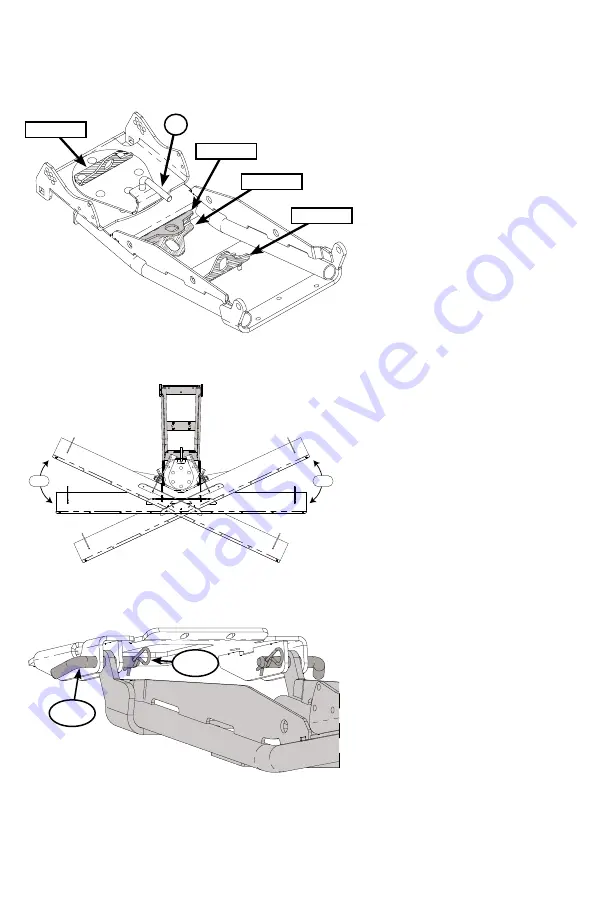
The tube system has 4 positions of
adjustment for the Lift Hook Bracket.
(The Lift Hook Bracket is what is used
to attach your lifting system to your tube
system.) Choose best postion for desired
lift height and cable/rope angle.
Position 1
is the default position
Position 2
uses the same bolt holes,
but in this case the bracket is flipped
over allowing more clearance
between winch and bracket.
Position 3
is used if the winch is in a
lower position in order to get a better
angle. Place the Lift Hook Bracket on
the bottomside of the push tube for
support.
Position 4
is used for machines where
the cable is at a severe angle. Such
as upper mounted winches. This
position will require longer bolts to
be installed.
7.
The tube system has three positions of
rotation for your blade. Each adjustment
is at 25 degree increments. In order to
make each adjustment you will need to
pull on the Pull Pin (Figure 4, Item 4.5)
and rotate your blade left or right until
you reach the desired angle.
8.
To attach the tube system to any KFI
mounts, position the tube system with
blade installed under your UTV. Raise
tube attach points to the mount and line
up the holes on mount plate with the
holes in the tube system. Insert Hitch Pin
(Item 7.4.2) through holes and secure
on other side with clip (Item 7.4.3) as
shown in Figure 6.
“Figure 4” Lift Hook Bracket Positions
POSITION 4
4.5
POSITION 2
POSITION 3
POSITION 1
“Figure 5” Blade Rotation Angle
25°
25°
“Figure 6” Tube System Attachment
7.4.2
7.4.3


