Remote device KFM 903A50
903A50
Parameter setting setup-level / Technical data
-Page 2 of 2-
_______________________________________________________________________
data subjects to alterations
903A50_e2.doc / 1510924
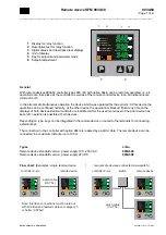
Hints for setup-level: The setup-level is entirely for the configuration of the remote device and is only used
exceptionally for adjustment of contrast and brightness of the background illumination, resp. for the
configuration of different bus addresses when using two remote devices. The control of the connected
controller in the operating mode is possible automatically after leaving the setup-level.
SETUP
Press and hold the
- button, switch on power supply
A frame with the description „SETUP“ shows the activated setup-level.
Release
- button,
continue to the next parameter and/or confirm entry:
briefly press each time the
- button
To change the setting displayed: Press the
...
button
Settings in detail:
(existence depends on version and type):
Factory setting:
Notes
Adr
bus address (0...10)
5
___
BRIG
Brightness adjustment for display remote device (0 ... 100)
50
___
return to operating mode:
briefly press the
- button
Error messages:
OFFLINE
Fault on remote interfaces, data link interrupted.
Check the patch cable and the controller 9.. power supply.
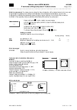
Technical data / Installation dimensions
903A50.:
Housing: for panel mounting, 96x96mm
Power supply:24 VDC,alt. 100..250VAC,app. 2 VA
Protect. system (DIN EN 60529):
IP 54 (terminals IP 20)
Permissible ambient temperature: 0...60°C
Nominal temperature: 20°C
Climatic category:
r
elative humidity <= 75 %
yearly average, no condensation
EMC: refer to EN 61326
Interface:
Ethernet 10Base-T or 100Base-TX
(autom. baudrate detect.)
, max. length 100 m
T
B
+0,8
H
+0,8
H=92mm, B=92mm, T=150mm alternative 70mm
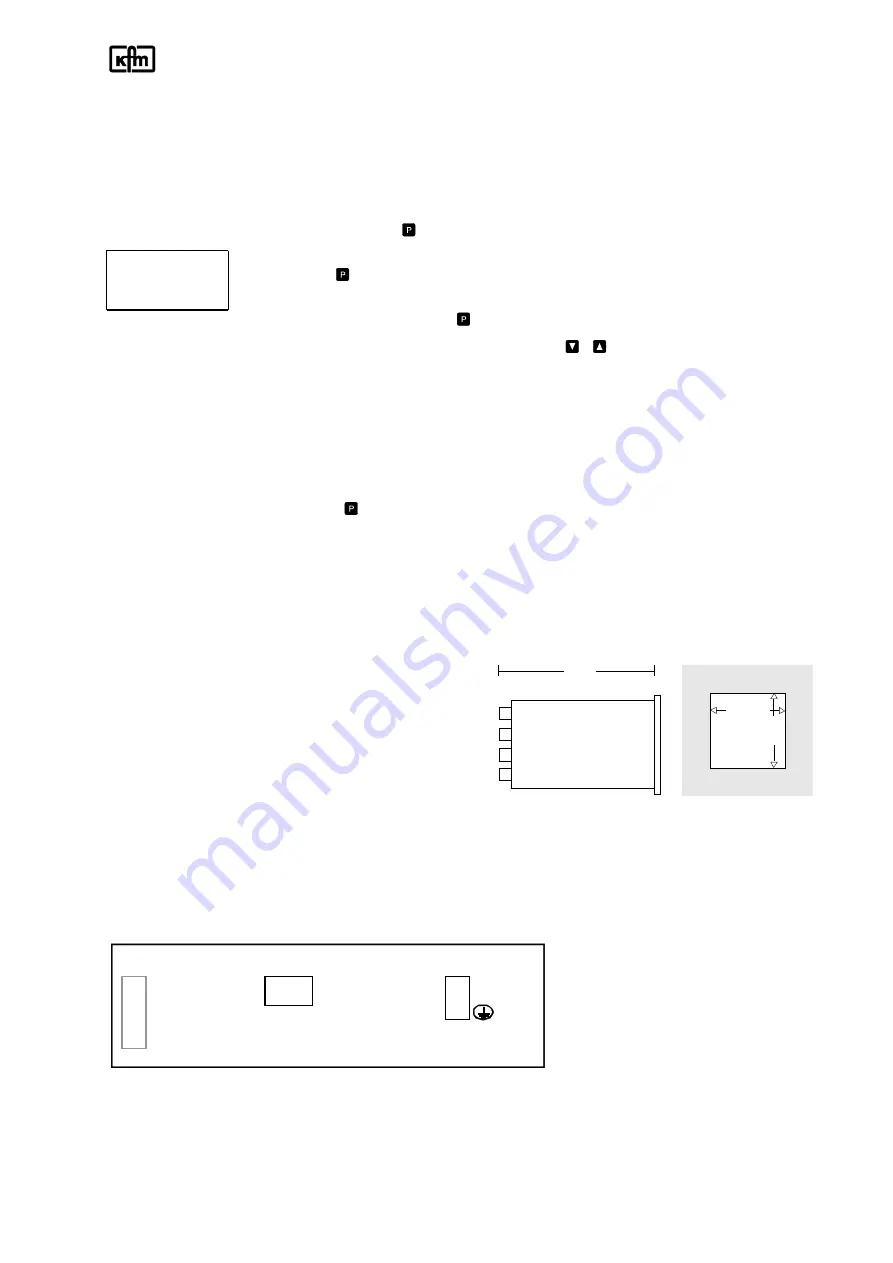
Wiring diagrams:
bin. inputs
remote-interface
power supply
b0 (-) 0V
to controller
27 L+
b1 P-key*
9..
28 L-
b2
29
b3 ^ key*
b4 v key*
f use T0,2A
*= depending on type
903A50.
(
Examples, valid for each device is the wiring diagram on its casing only


