background image

Summary of Contents for GT44185A

Page 1: ...151349 03 11 96 KFsW PRINTED IN U S A ...

Page 2: ... on sleep _ opes IILCHILDREN Tragic accidents can occurif theoperatoris no aledto he presence of children7Chll rd_n are often attractedto the machine and the mowing activity _iNever assume that qI_ d r_g_wIll remairl whereyou last s_w them _ Keepchildren outof themowingareaandundertheW_tehiu dai eblano herresponslbleadu t _ Be i_ledandummachneo fch dredener hearea Beforeandwhenbacking look behinda...

Page 3: ...an Ja PRODUCT SPECIFICATIONS HORSEPOWER 18 5 GASOLINE CAPACITY 5 GALLONS AND TYPE UNLEADED REGULAR OILTYPE API SFiSG SAE 30 above 32 F SAE 5W 30 below 82 F OIL CAPACITY 8 0 PINTS SPARK PLUG CHAM blON RJtgLM GAP 030 VALVE CLEARANCE INTAKE 004 _ 006 EXHAUST 007 009 GROUND SPEED M_H FORWARD tst 7t 2rid 1 4 3rd 2 41b 3 2 51h 4 1 61h 5 3 REVERSEr 1 6 TIRE PRESSURE FRONT 14 PSI REAR IO PSI CHARGING SYST...

Page 4: ...ed Belt s _ c H Remdva Aep a amen 21 _ _ _ Fuse 23 Blade i_ _ _ _ Hciod Rernova nsta_l tlon 23 Hood RemovaMnslallation 23 Motion Drive Belt _ Rem6val Replacement L 20 Reelacement L _ 16 L Mower Be t s 2 t Brake Adjustment 2 Leveling Mower Deck 20 RemovaVReplacement C Chfirt r _15 Front to Back 2C Carburetor Adj Jstment 25 Engine 17 Bide to Side L _ _ _ 19 Controls Tractor 11 Mower RembvaHnsta latl...

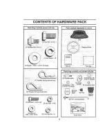
Page 5: ...oop 2 Hex Bolts 1 4 20 x 3 4 2 Mex Nuts 1 4 20 2 Washers 9 32 x5 8x16Ga 2 Lock Washers 1 4 Parts packed separately in carton steering Wheel i I I i _ Manua Parts Bag Parts bag o ntentsnot shown full size 5 16 x 12 Gauge _ _ Steering _ _ Wheel nsert 2 Keys _ 2 F o t_t Unk _ssemb es steerlrig Sleeve Slope Sheet ...

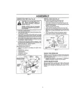
Page 6: ...emove mowerand packing materiale_ r Checii i0r any dditional Joose_ pads or cations and BEFORE ROLLING TRACTOR OFF SKII3 R moVeieci nutand large fiat washer fi o ste0rie sl_aft Postti_J_ front Wheei_oithe tractor so they are pointlng stratghtfo ar d _ z i S de the steedng sleeve overihe steedng shaft Posttlod steenng wheel so cross bars are honzontal left to _lght and slide or_t6adapter _t Secure ...

Page 7: ...ex NUT__ W SHER WASHER DISCARD LreRM NAL HEX PRO Eq TWff CAPS BOLT _ _ _ _ CASL_ _ NEGATVE NSTALL_ sEAT See Fig 3 Adjust Seat before tightening adjustment bolt Remove cardl cardpack ng on sea pan F lac_ seat oil seat pen arid assembleshoulder bolt Assemblea d ustmentboff ocl_washei andllatwasher loosely qno t gbtan YightensEoulder bait securely Lower seat intoaperat r g position and sit on seat Sl...

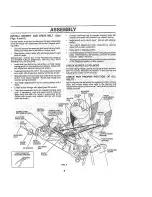
Page 8: ... _rake Cut and remove ties secudng anti sway bar and belts_ Swing anti sway bar to left side of mower deck Slide mowerunder trac or w hd scharge guardto right stde of tractor IMPORTANT CHECK BELT FOR PROPER ROUTING IN ALL MOWER PULLEY GROOVES INSTALL BELT INTO ENGINE PULLEY GROOVE Installone front link intophole of theL H front mower bracket and LH frontsuspension bracket Retain with two slt_gleIo...

Page 9: ...the factory _i Z Be s_re mswer aecl_is p_periy leVelea side lo side front foq ea fOf bes cPttlng results Tl esmust be properly inflated for levelihg _ Check mo_ei _ ndddve beltsl Be sure they arerouted properly around pulleys and nside all belt keepers 2 eh_ _Wi ng S_e that all connections are stillsecure and wires are properly clamsed WHILE LEARNINGHOW TOUSE YOURTRAC _ OR PAY EXTRA ATTENTION TOTH...

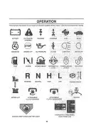
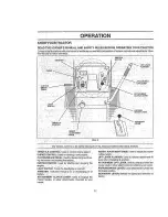
Page 10: ... REVERSE _ i i ENGINE OFF OIL PRESSURE CLUTCH LIGHTSON _ LIGHTS OEF mxJ CHOKE MOWER HEIGHT Dd E R E Nf_ AL PAR KIN a_R AK_ I OfiLOCKED LOCK_ _ LOCKED REVERSE NEUTRAL H HIGH LOW PARKING BRAKE MOWER LIFT ATTACHMEN 1 ATTACHMEN _ CLUTCH ENGAGED OLUTCH DISENGAGED GNITION II_ C_ _ _ T_ _ _ _ _II DANGER KEEP HANDS AND FEEl AWAY HYDROSTATIC FREE WHEEL Hydro Models oniy 10 ...

Page 11: ...KNOB Used to adjust the mower CHOKE ONTROLi Used for star tEhg a cold englne cutting hetgh CLUTCH BRAKI_ I_EbAL UsecJfor cJeclutcilln_ andforak LIFT LEVER PLUNGER Used to release attachment lift Ingthe tractor and stad ng the engine IEve when changing its posIUon IGNITION Sw rcH Usscl iors artng and s oppng he ATTACHMENT LIFT LEVER Used ioraiseandlowerths engine _ t LIGHT swiTcH Turns the headiigh...

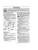
Page 12: ...rass areas I _A CAI JTIoN Always stop tractor com _ plately_asdesetibed above befbreleav _ mg the_operat0r s position to empty grass catcher etc TO USE THR 0_LE CONTROL See Fig 6 _iwa_ s ope _at _ngine at full ihrotile OperaJJrlg erigine at less thanfull throttle reduces ths batterycharging rete _ FiJII hl 0ttl_o fers th6 bes mower uerfbrmanca TO USE CHOKE Ce_ITROL See Fig 6 LJse cho_e con_roi whe...

Page 13: ...wly releaseparkingbrakeand clutch bt ake pedal Ualie_ll iUfh_ sl0wly TO TRANSPORT Raise atlachment lift to highest position with attach ment liftcontrol When push ngor 0wtngyour tractorbesure gearshift lever ISinneutral N position Do hgt pg_h Sr tS_ tractor ai mo re than five 5 M PH NOTE _TO pro eciiho0d from dama gewhen transporting your h actorOna truci_ora trafie besure hoed Iscloeadand secured...

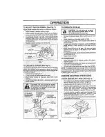
Page 14: ...e prdpe_ lyleveled f0r b_Sl mowtng carbure or cleans producls in the fueI tank or permanem performance See TO LEVELMOWER HOUSING In damage may Oceur _ _ _ th eSeryiceand Adjustments section of this manual use the _ unner 0n the righi hancl side of I nowera_ a _ i _ _ CAUTION_ Fill to bottom of gas tank gu de The bade cu s approx ms e y an nch outside _ _ filler heek_ DOnotoverfill Wipe off any t_e...

Page 15: ...t h ave _SPINDLE ZERK SPINDLE ZERK _ been subjected tO operatoi abuse or negItgehce To rece vefbll valuefromtheWar_ anly operate rfiust maintain trect6_ as lhstrhcte_l In this manual FRONTWHEEL _ Some adjustments Wi l need to be made periodically tc FEARING ZERK pr0periy maintain your tractor Ai _d ust_enis ihihe Ser vtceand djustments section of thlsmarlual si_ouldbechecked at least once each sea...

Page 16: ...mpt to sharpen while onthe mower TO ch_ck biade _alance yodwill n eeda 5 8 aiameier steelbolt pln_oragone balancer When tJ_lnga cqne balander fo low heInstructions supplied with bal Slide bladeOntoanur_threadedpodionof the_teel bolt oi pie arid hold the b01tDrpin parallel with the ground If blade Is balanced I should remaifi in a horizorital posltIDn If eithei end of the blade moves dowriward sh q...

Page 17: ...rs in orie yea Cl_ecl4 the _rankcase oli level befo estarting the engine and after each eight 8 hours of opera ton Tighten eil fill cap dipsfick securely each time yeu checkthe oil level TO CHANGE ENGINE OIL iSee Figs 13 find 14 De ermine temperature range expected before oil change All ell must nieet API service ClassificationSF or SG Be sure tractor is en level surface Oil will drain more freely...

Page 18: ...lns aii pro cleaner 5_iarcarkridge Ralfistall cover an_Jsecure Vilihknob s propedy posriloned _ _ TO SERV CE CAE_TRDGE mmediately WipeUp any spilled gasoline Remove w ng nu sand cartridge p ate Carefully remove cadridge o prevent debris from an CLAMP __ _ i CL_ Mp ii _ taa_cartfldg abytapl_lnggahtlyo lflats6rfacg livery dirty 0rdamaged replace cadndge i_ Rensa cartrdgepate Wngnus preceanar cove_ a...

Page 19: ...19 _letsemowei to ils highest posigoh Measure he ght from bottom of deck curl to ground level at front corners of mower 3lstaRce A on both remove links Slide mower forward and removebell from engine pulley _ _ Siidem 0 er out from under riga side of tractor IMPORTANT IFAh ATTACHMENT OTHER THAN THE MOWER DECK IS TO BE MOUNTEEON THETRACTOR REMOVE THE FRONTLINKS _ TO iNSTALL MOWER _ F_liow 6 rocedure...

Page 20: ...lated around mandrels and entire upper deck _ _both fi on links are equ l in 16ngth su_ace _ r i i O it itnks _ L e r_o_ equ l ih lehgtll ad _s one link o same Oi_eckpr lmaryicJl_r _ m and two lcllersto see thatthey ler_gth as otherllnk rotatefreely front n s an equa number of turns _ nsta beltfnhoh d ers Makesura_elt s nbothbe _ vvnen is arise t is 1_ o 1 2 _ower at rent teen _e a_ th IHler s S o...

Page 21: ...beltIsIn all g ooves pi operly Rec6nnsc secondary ciutcll rod to pivot ad with retainer _pdng _f Fie flsta i B_H m_ndralebverr _ F_elnsiall_ower t0 iract0r See INSTALL MOWER AND DR VE BELT n he Assembly seclon o his i rfiadUal _1 _ k ReSssembl6 mowe_ drive belt See TO REPLACE MOWER DRIVE BELT In thtsSection o th s manua PIVOT RETAINER i SPRING TO ADJUST BRAKE See Fig 24 YoUr tractor is equippedwit...

Page 22: ... steering wheel crossbars aie n01horizontal leftto righti _vhen wheelsareposilldned stralghtforward removesteer rng wheeland reassemble per Instruetlons EntheAssembly seetior_of thismanual FRONT WHEEl TOE IN CAMBER The front wheel toe in and camber are notadjustable on your tractor If damage has occurred to affect the front wheel toe In dr camber contact your nearest authodzea servlce cen eddepart...

Page 23: ...a panel bolton the leflSid _0fthetractor away from fuel lank andbatte_ _ i TO REMOVE_CABLEBIREVERSE ORDER _ BL _CK cable firsi from chassls arid fu ly charged R_D _ab_eiasi from l_oth _atterles BOLT FIG 29 TO REPLACE HEADLIGHT BULB Raise hood Pull bulb holder out of the hole In the backside of the grill Replace bulb In holder and push bulb holde_securely r back Into the hole Ir_the backside of the...

Page 24: ...ten bable clampscrew securely TO ADJUS_ CHOKE CONTROL See Fig 32 The clacks co ntiol _asibeen pieset at the acio_ and _ adjustmentshould not beneces_aly_ Check adjustment as described below befe_ eloosening cable if djbstment is necessary proceed as follows W h eng ne not _nnlng move choke control iibcated on dash panel to full choke 1 4 position _ Remove a I ceaner c0ver f er _nd c rtr idget late...

Page 25: ...OR PROPER ENGINE SPEED OVERSPEEDINGTHEENGINE ABOVE THE FACTORY HIGH SPEED SETTING CANI BE DANGEROUS IF YOUTHINKTHE ENGINE GOVERNED HIGH SPEED NEEDS ADJUSTING CONTACT YOUR NEAREST AUTHORIZED SERVICE CENTER DEPARTMENT WHICH HAS PROPER EQUIPMENTAND EXPERIENCE TO MA_E _ ANY NECESSARY ADJUSTMENTS _ _ _ and the throttle control y see IDLE SPEED IDLE MIXTURE SCREW in ciockwise ceunfe_cockr LEVER FINAl cb...

Page 26: ...ttery termlnals Be sure batiery drain tube Issecurely attached if batlery is removed from tractor for storage do noL store battery directly on concrete or damp surfaces ENGINE FUEL SYSTEM MPORTANT IT S IMPORT _NT TO PREVENT GUM DEPOSITS FROM FORMING IN ESSENTIAL FUEL SYSTEMPARTSSUCHAS CARBURETOR UELFILTER FUEL HOSE OR TANK CURING STORAGE ALSO EXPER ENGE NDICATES THAT ALCOHOb BLENDED FUELS CALLED G...

Page 27: ...n 3 Walt several minutes before agempflng f0 slap d Reolace spark plug 5 Clean reotaca air tilter R_place fuel fleer 7 Drainfuel tank and carbulelor refilltank wgh fresh gasoline and replace fuel filter g Checl_at wlIIng i 9 Cont bt a_ eulhorlzed service center department 10 Contacl an auihodzed service center depadment 1 CIeafffroplaco air tiger 2 Replace spalk plug B Recharge br replace baffery ...

Page 28: ... 3_ Faugh light s_i lt oh 4 _ L_s_ ord_agad w ling 5 Blown lusa Z Poor cable Oonneciions 3 Fault_ egulator If sO eqt_tppaci 4 F_ulty alternator t r I Engln_ ll Ir oig cqnimi not ei al SL0W pqsitpq for 3g see6nds before slopping engine CORRECTION l Check wMng swltch_S andconnecgons if not cerrected contactan authorized service cenlad deparlmeni o ooo b o o gh e obe 2 LBvolmowordeck 3 Clebr_ui_dersl...

Page 29: ...TIJqGSYSTEM 1 4 _ ___ I OUT_UT D ODE ALTERNAT 3R I tl _ AMP AO _8_00 RP_ I YOURTRACTOR S I_ _ EQUIPPED WITH A SPECIAL HEADL GHTS ALTERNATOR SYSTEM I I _ _ ELIGHTSARENO CONNECTEDTOTHE i _ _ _ _ J I BATTERY BUTHAyETHEIR_ _ I_E AD IgHf _ _ I OWN E_ECTRICAL SOURCE SWITCFI L O _ A a BECAUSE OETHIS THE OFF C J BRIGHTNESS OF THE LIGHTS WILL CHANGE WITH ENGINE SPEED AT IDLE HE LIGHTS WILL DIM AS THE ENGIN...

Page 30: ...REPAIR PARTS TRACTOR MODEL NUMBER GT44185A ELECTRICAL 22 42 41 49 12 28 30 ...

Page 31: ..._ _ fra_jBattery 7 80 X 5 26 BIk Clamp Hose Olive Boit RdHd Sqnk 1 4 20 x 7 1 2 GuardTermtnal BIk Nut Push Nylon 1 4 Battery Switch Interlock Push In Washer Lock 1 4 Nut Jam Hex 1 4 20 Uric Harness Asm Light W 4152 BulbLIght _1156 _ CableGround 6 Ga black Cable Battery 6 Ga 22 red Fuse 30 AMP Auto G_ een Cable Battery 6 Ga 21 bla0k Sw chPerfger Swltchlgn3pos _ N0tlgniti0n C0verSw Key BIk l 26 Text...

Page 32: ...REPAIR PARTS TRACTOR MODEL NUMBER GT44185A CHASSIS 17 35 45 26 25 2B 31 90 115 44 3 102 B4 87 33 10 2B 32 ...

Page 33: ...39887 Bracke_Assy Pivot RH 44 140675 SlrtpAsm Fender 45 132257 Bezel HeadLight 47 105531X Nut Push 50 124048X Baffle Hood 59 110436X BushingSnap Splil 60 72140606 Bolt dhd Sank 3 8 16 UNC x 3 4 64 150272 Dash Lower 55 74760532 Bolt Hex 5 16 18 x 2 Gr 2 66 140942X011 Plate i 71 73640400 Nut Keps Btk Hex 1 _4 20 UNC 72 110350X550 AssyS rap Fender _ 74 73680600 Nut Oi owniock 3 8 16 UNC 123764 X550 A...

Page 34: ...REPAIR PARTS TRACTOR _ MODEL NUMBER GT44185A DRIVE 57 72 52 1 26 27 34 ...

Page 35: ... 85 150380 38 123674_ Idler Flat 86 71208 89 74760644 Bo_ He _Head 3 8 16x2 3 4 87 19212018 40 4470J Spader_i _ 88 12000008 41 753399 Keeper Belt 89 139992 42 19131312 Washer 13 32 x 13 16 x 12 Ga 90 124346X _t 105706X Bearing 98 14497H 45 110812X Washer Hardened 110 74760612 46 12000039 Riilg Clip _ill 123776X 47 127783 Pulley idler V Groove 112 19091216 48 123789X BeUcrankAsm Cuch 115 19132203 4...

Page 36: ...REPAIR PARTS TRACTOR MODEl NUMBER GT44185A STEERING ASSEMBLY 36 ...

Page 37: ... Asm Stig Washer Thrust 515x 750X 033 Support Shaft Washer Shim 1 4 X 5 0 X 062 Washer Lock Hvy Helical 1 4 Screw Cao Socket Hd Phos Oil Shaft Asm Ptttman Nyllne_ Snap In Bracket Steering Geai Sebt0r 22 Teeth Screw Thdrol 3 5 16x3 4 Ty ft Pin Cotter 1 8 x 3 4 Bracket Pvt Ma CI Lvr TieRed Washer 11 32x3 4x 16Ga Washei_Lack Hvy HIcI Set 5 16 Locknut 5 16 24 UNF Bushing Strg BIk 3 4 angle Screw Tit 1...

Page 38: ...REPAIR PARTS TRACTOR MODEL NUMBER GT44185A ENGINE 32 39 37 33 29 0P i_IONA_ EQUIPMENT Spark Arrester 38 ...

Page 39: ... 1 1 2 Tt 25 136672 _ Control Choke 51 00 BIk W bend 26 73920600 Nut Keps 3 8 24 Unf 27 152927 Screw z 28 73680600 NutCrownlock 3 3 16 UNC 29 137180 Kit SparkArrestor 31 151346 TankFuel 32 14052 7 Cap Asm Fuel Too Vent W Lany 33 123487X Clamp Hose BIk 34 106082X 37 9543R 38 39 109227X 40 3645J 41 139277 47 100229L 48 135029 Pad Spacer Line Fuel 54 Plug O 1D aih Order Erom Engine Manufacturer ad Id...

Page 40: ...REPAIR PARTS TRACTOR MODEL NUMBER GT44185A SEAT 6 17 12 4O ...

Page 41: ...Seal Clip Push In _ Nut l_SckHex w Iris 3 8 16 UNC Spring Seat Cprsn 2 250 BIkZI Pan Seat Bracket Mounting Switch BLUshing Snap BIk Ny150 Id Bolt Rdhd Sht NR1 4 20xl 3 0 Spacer Split 28 X 98 Spring Cprsn Rate Nut Lock 1 4 Lge Fig Gr 5 Zinc Bolt Shoulder 5 16 18 Unc 2A Nut Crowniock 5116 18UNS Bolt Fin Flex1 2 13 X 7 8 Gr 5 Washer 17 32 X 1 3 16 X 12 Ga BoltShoulder 5 16 18 X 62 Washer Loci Hvy HIc...

Page 42: ...REPAIR PARTS TRACTOR MODEL NUMBER GT44185A MOWER LIFT i 47 14 f 6 13 32 42 ...

Page 43: ...9553 Arm_ Suspenelon_ 20 3146R Retainer S_srlng _ 23 110807X Nut He Speda 2 19131016 Washei 13 32x5 Sx16Gauge 25 137150 Sprng 2 26 76020308 i Pin C61ter_3 32 _ 1 27 137167 Rod Adjust Lift i _ 26 73350600 _ Nu Hex Liam 3 8_16 29 135057 _ Kno_ nfInite Height AdJustment 30 150233 Trufinion _ i 31 140302 Bearing Pvt Lift Spherical 32 73540600 Nut Centerlocl_ 3 8 24 39 142992 _ Stop OverCentei _ 42 736...

Page 44: ...72 77 23 ...

Page 45: ...58 105455X Wheel Gauge 59 4898H Bet Shoulder 60 139031 6 136573 63 72110612 64 19121 414 65 151831_ 66 139622 67 73930600 68 140364 69 74760612 Pih Clevis Bracket Wheel Gauge Bolt Carriage 3 8 16 x 1 1 2 Washe_3 8 x 3 4 x 14Ga Pulley IdlerFiat Mower Keeper Belt Idler 50Vent Dr Nut Centerloek 3 8 16 UNC Brackat Pot 44 Mech _ Bolt Fin He _ 3 8 16UNO x 3 4 70 140361 _ _acketr S_PrdPbnrteBrake 44 Mech...

Page 46: ...REPAIR PARTS _TRACTOR _ MODEL NUMBER GT44185A PEERLESS TRANSAXLE MODEL NUMBER 820 0i69 46 ...

Page 47: ...h 71A 792145 Pushnut i Beve Gear S eel 16Teeth 72 _792165 Threaded Pluc 9 16 18 ORn Beve Pnon See 10Teeh 72A 788091 _ g RhgGearl 79 792144 Spring Ddve Bee 81 Z86081 _ RollerChain Dr ve P n I _ i ci__ il _ Number 41 Chain 24 Links Neutral Spacer 360 340 The 82 786082 SDrocket 9 Teelh Reverse Nelurat Spacer 276 268 Thick 83 780123 Sprocket 18 Teeth Reverse Stee Ba 5 16 Dameter 84 786131 Bearlng Cap ...

Page 48: ...c6 KEY PABT NO NO DESCRIPTION i I 2 65139 ly 3 278 4 4 106230X 4 140183 Tire _ 1 5 5990_ _ _ Tube Froi_t SeWlceltemOny 5 7t52_d1 Tube Rear Servlse Item Only 6 ld622BX551 Rim Asff hB I_oht Seiv c e 6 12407 X551 R rqAsm 12 rearServi_De_ 104757X Gap Axle BIk I 50 X I O 8 9040H Be_rlhg FIB nge F_ ont Wheel Only 144334 Sealant Tire 10 ounce Tube NOTE All component dimensions given in U S riches I Inch ...

Page 49: ...49 ...

Page 50: ...50 ...

Page 51: ...can only oe Wisconsin At hellme of equestlngwarranty t charges for ma _ng serv ce calls a purchaser shaIIb part s of Ihe _ 1 _ I_es i ExPREsSED WARRANTY IS IN LIEU oF _ LL OTHER EXPFiESS WARRANTIES Neilher Tecumseh noi ani of ils a aesma asanywarran es iepreaena one arpromsaa w anorora as _ hequalyof hePowarTra nComponentoranyoHIs pads btherlhanassetforthherain_ _i i 1 _ _ _ _ i _ 1 ANY IMPLIED WA...

Page 52: ... SUGGESTED GUIDE FORSI L _ ONLYRIDE UPANDDOWN HILL NOT ACROSS RILL r ...

Reviews: