background image


KGUARD Standalone (KG-SH330&SH530) User Manual                                                                                                                                     

www.kguardsecurity.com


15 


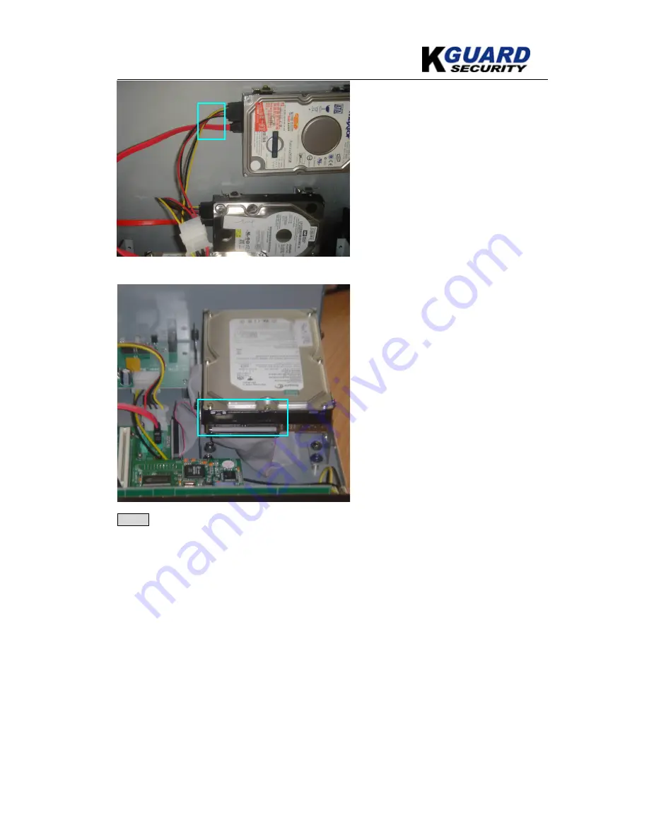
Figure 5- SATA connection             


Figure 6- IDE connection


Step 5 : Properly connect all the appropriate cables & power cables to their respective HDD as 

shown in figures 5 & 6 for both SATA & IDE. 


Summary of Contents for KG-SH330

Page 1: ...KG SH330 SH 530 User s Manual Default account Password for KG SH330 530 User Account aa Password 11 Version 1 0 ...

Page 2: ...reen 19 7 Menu 20 7 1 Login Logout 21 7 2 Status 22 7 3 Volume 23 7 4 Video Adjustment 24 7 5 VGA Display 25 7 6 Backup Device 26 7 6 1 Backup Setting 27 7 7 Setup 28 7 7 1 Pre Camera 29 7 7 2 Camera 30 7 7 3 Alarm 34 7 7 4 SEQ Display Setup 36 7 7 5 Scheduled Record 37 7 7 6 HDD 38 7 7 7 Password 42 7 7 8 System Setup 43 7 7 9 RS 232 422 485 44 7 7 10 Network 46 8 PTZ Control 50 9 Software Upgrad...

Page 3: ...ista 96 12 CMS2000 101 13 POS Connection 102 13 1 Connection Step Diagram 102 13 2 P O S Setting of Standalone DVR 102 13 2 1 RS232 422 485 Setting via Local 102 13 2 2 RS232 422 485 Setting via Remote 106 Appendix A POS Connection Diagram 111 Appendix B POS 111 Appendix D Detection Setting 113 Appendix E Time Zone 114 Appendix F Recording Table Reference NTSC 116 Appendix G Recording Table Refere...

Page 4: ...x1 1 7 Power Cable x1 1 8 Bolt x9 1 9 AAA Battery x2 1 10 SATA Data Cable x2 1 11 CD x1 1 12 User Manual x1 1 13 Touch Board optional x1 Used to cover the POS Printer connection terminal when the unit is not connected to any of this external device KG SH330 Remote Controller Y Cable Terminal Block RS232 Terminal Cover Power Adapter Power Cable Bolt AAA Battery SATA Data Cable CD User Manual Touch ...

Page 5: ... devices supported for RS 232 port SH 330 up to 9 POS SH 530 up to 16 POS GPS PTZ keyboard control via RS 232 and RS 485 Optional IEEE 1394 connector for external HDD RAID extension HDD failure action supported DDNS for static IP supported Multi level password and authentication key protection to ensure high degree of security More user friendly OSD with some new icons Multiple event playback back...

Page 6: ...era Motion Alarm Pre record time 0 60 seconds Post record time 0 60 minutes Network Function Ethernet RJ 45 x1 Protocol TCP IP HTTP PPPoE DHCP DDNS FTP Remote Access IE up to 4 DVR CMS2000 up to 600 channels Remote stations PDA PC Mobile Phone Control IR Remote Controller Yes RS 232 1 x D type female connector for PTZ POS GPS RS 485 422 1 x RJ 45 for keyboard PTZ control Other Function Motion Dete...

Page 7: ...ct the unit to cameras video input terminal 2 Video Output Connector Connect the unit to cameras video output terminal 3 Audio Input Connector Connect to the external audio device 4 75 Ω Terminal Set each DIP switch to ON unless the corresponding video output terminal is connected 5 Audio Output Connector Connect to devices such as speakers 6 COM RS 232 Connect to GPS or POS 7 RS422 485 switch All...

Page 8: ...hard disk box 16 VGA connector Connect to VGA monitor 17 AC Cord Inlet Connect the unit to the power source 18 Main Out Connect to the main monitor for display for composite video 19 Main AUX In Out Used to daisy chain to TV monitor This has the same output function as Main Out but can be switched off via RS485 keyboard control Please cross reference to Appendix I for connection detail 20 Call Mon...

Page 9: ...e unit to cameras video output terminal 3 Audio Input Connector Connect to the external audio device 4 75 Ω Terminal Set each DIP switch to ON unless the corresponding video output terminal is connected 5 Audio Output Connector Connect to devices such as speakers 6 COM RS 232 Connect to GPS or POS 7 RS422 485 switch Allow the selection of RS422 or RS485 8 RS422 485 port Connect this to the compati...

Page 10: ...Inlet Connect the unit to the power source 18 Main Out Connect to the main monitor for display for composite video 19 Main AUX In Out Used to daisy chain to TV monitor This has the same output function as Main Out but can be switched off via RS485 keyboard control Please cross reference to Appendix I for connection detail 20 Call Monitor Output Connect to the monitor for call monitor display 21 CA...

Page 11: ... camera supported Goto Click to view the image taken by PTZ camera at its preset location Function Click to add an audio recording feature Set Click to switch between GPS and POS Display and to reconfigure the display setting Please refer to Appendix C for detail setup Zoom Press to adjust the zoom of the camera 8 Adjust Click to switch between different display layouts 9 Menu Press to access the ...

Page 12: ...to play or pause the playback Forward feature Click to copy an image to an external storage device Click again to stop copying Stop the playback I Click to skip to the next image 15 Page Press to scroll up down the log list 16 DVR1 DVR8 Click to access the respected DVR when there is more than one DVR connected within a network Please refer to Appendix J for setup detail ...

Page 13: ...on either the 4 th HDD or the VGA card can be applied once at a time Figure 1 Step 1 Uncover the system case Figure 2 Step 2 Screw both the SATA HDD tightly onto the HDD racks of the upper metal case as shown in the figure above Figure 3 Step 3 Before attaching the 3 rd the 4 th HDD to the lower metal case carefully fold the IDE cables in the orientation as shown SATA HDD IDE cable HDD rack for ID...

Page 14: ...the IDE onto the HDD rack provided on top of the IDE cable as shown in the figure Note Although this system can support up to a maximal of 2 SATA HDD 2 IDE HDD the 4 th HDD is optional If the 4 th HDD is to be installed VGA card must first be removed to accommodate for space limitation IDEs VGA Card ...

Page 15: ...30 SH530 User Manual www kguardsecurity com 15 Figure 5 SATA connection Figure 6 IDE connection Step 5 Properly connect all the appropriate cables power cables to their respective HDD as shown in figures 5 6 for both SATA IDE ...

Page 16: ... installation Step 7 Make sure to install at least one hard disk drive inside the hard disk tray If there are two HDDs please set both HDDs as 1 master for two independent cables 2 master slave for one cable with two connectors or 3 cable select The settings should be described on the HDDs or in the manuals come with the HDDs Note 1 Whether the upper HDD or the lower one is set as HDD 1 is fine fo...

Page 17: ...e it can be used to record video audio Please refer to Section 7 7 6 1 HDD Format Clear to format the HDDs Note 3 Please refer to the following diagrams if IDE to SATA converter board is used Appendix M IDE TO SATA Converter Board Installation Guide Please make sure to set the master slave jumper on the board correctly ...

Page 18: ... on the screen NOTE Call monitor button is not functional during text numeric entry 7 2 Press to enter the available number and letters shown on the screen 8 4 Press to enter the available number and letters shown on the screen 9 Press to enter the code for the selected foreign languages A MUTE Press to enter the available number and letters shown on the screen NOTE Mute button is not functional d...

Page 19: ...video 2 Camera ID Shows ID number of the camera 3 Time Date Shows the current recording time and date 4 Audio When audio is turned on audio icon will be displayed on the screen 5 Alarm recording percentage Shows the percentage of alarm triggered recording 6 Normal recording percentage Shows the percentage of normal recording 1 2 1 3 4 5 6 ...

Page 20: ...t User can adjust the color hue saturation contrast of the video image 5 VGA Display User can adjust the image output quality in terms of resolution brightness contrast hue and saturation 6 Backup Device This window allows user to view the connection status of the backup device and to initiate data backup 7 Setup System features settings Please refer to section 7 7 for detail information 8 Softwar...

Page 21: ...ithout making changes Name Description 1 Login Name Please refer to section 5 for text numeric entry Note The default login name is aa 2 Password Please refer to section 5 for text numeric entry Note The default password is 11 3 Login Click to login into the system Note The control buttons will be unlocked after system login 4 Logout Click to logout of the system Note The control buttons will be l...

Page 22: ...ption 1 Alarm record size record percentage It shows the size of data in Gigabytes GB for alarm recording mode It shows the size of data for alarm recording mode 2 Normal record size record percentage It shows the size of data GB for normal recording mode It shows the size of data for normal recording mode Motion A white box for a specific camera appears upon motion trigger 3 Cameras Camera video ...

Page 23: ... display press to change the highlighted option to Volume and then press ENTER to call up Volume display as shown below This feature allows user to setup the volume for each audio input up to a maximal of 4 audio inputs for recording purpose as well as the volume of the video during playback Press these buttons to select the items ESC Press this button to escape from this screen and return to MENU...

Page 24: ...s shown below This setting allows user to adjust the quality of the video Press these buttons to select the items Name Description 1 Brightness Press to adjust the Brightness 2 Contrast Press to adjust the Contrast 3 Hue Press to adjust the Hue 4 Saturation Press to adjust the Saturation 5 SEQ CALL Click to apply the default video setting either to this camera or to all cameras 6 MODE Click to res...

Page 25: ... these buttons to select the items ESC Press this button to escape from this screen and return to previous display If the contents have been modified a Save dialog will be shown to ask the user to save the changes press ENTER to exit and save ESC to exit without saving Name Description 1 Resolution Press to adjust the Resolution 2 Brightness Press to adjust the Brightness 3 Contrast Press to adjus...

Page 26: ... the connection status of external storage device Connect Disconnect If the specific backup device is disconnected as shown in Current Status please plug the USB device in one of the USB ports of the system and or insert a DVD for DVD device and then press ENTER to command the system to connect with the device If the specific device is already connected EX Read write as shown in Current Status ple...

Page 27: ... Description 1 Backup Device Click to select the storage device for the backup 2 Backup Speed Click to adjust the backup process speed 3 Directory This will display the directory path of the backup file 4 Cameras The cameras that are selected for data backup will have a white colored box 5 GPS File Format Click to set the GPS file format to be saved 6 End Time Click to set the backup end time in t...

Page 28: ...the IE interface of the system and press to locate the data file Attention 2 Please refer to Appendix K Standalone DVR Hardware Accessory Support List 7 7 Setup In Menu display press to change the highlighted option to Setup and then press ENTER to call up Setup display as shown below Press these buttons to select the items ESC Press this button to escape from this screen and return to MENU displa...

Page 29: ... escape from this screen and return to previous display Name Description 1 REC Resolution Press to adjust the recording resolution to 360x240 720x480 or 720x240 2 Watermark to record with digital watermark or not If yes all the recorded images for all the cameras will have digital watermark embedded Press ENTER or to check uncheck this item The default setting is checked 3 Camera This shows the nu...

Page 30: ...er motion detection recording quality and recording rate Press these buttons to select the items ESC Press this button to escape from this screen and return to previous display Name Description 1 Camera The number corresponds to the camera supported 2 Title User can assign a title to different camera for identification purpose Please refer to section 5 on text numeric entry 3 Video Loss Settings A...

Page 31: ...or level users can view the live video of the respected camera 7 Call By Event Call Monitor This feature will cause a specified channel to display upon a specific event trigger 8 Dwell Time User may adjust the value to determine the display time of the call monitor 9 Audio The audio setting allows user to turn on off the sound recording option 10 Record Quality Press to adjust the recording qualit...

Page 32: ...1 3 PTZ Control 4 Pre record Press to adjust the transition period before initiating the recording prior to motion detection 5 Alarm Out Click to select the video loss triggered alarm output 6 Buzzer Press Enter or to check or uncheck this item To activate the buzzer warning that will be triggered upon video loss 7 Log Press Enter to adjust Enable Disable When enabled the system will record all vi...

Page 33: ... a motion please refer to Chapter 10 1 3 PTZ Control 3 Pre Record Press to adjust the transition period before initiating the recording prior to motion detection 4 Post record Press to adjust the transition period before initiating the recording after motion detection 5 Alarm Out Press to select the motion triggered alarm output 6 Detection Settings This setting allows user to define the area for ...

Page 34: ...heck event message being displayed on the screen 7 7 3 Alarm In Setup display press to change the highlighted option to Alarm and then press ENTER to call up Alarm display as shown below This feature allows administrator to define the condition for the alarm to be triggered Press these buttons to select the items ESC Press this button to escape from this screen and return to previous display Name ...

Page 35: ... specific event 8 Buzzer Press Enter to check uncheck this item To activate the buzzer warning due to an alarm trigger 9 Log Press Enter or to check uncheck this item When checked the system will record all video loss history A Screen Message Press Enter or to check uncheck this item Choose enable check disable uncheck event message being displayed on the screen B E mail Press Enter or to check un...

Page 36: ...oth main monitor and call monitor Press these buttons to select the items ESC Press this button to escape from this screen and return to previous display Name Description 1 Total Pages Press to set the total of display channels for each screen 2 Dwell Time Press to set the display time 3 60 seconds of each camera for each sequential rotation 3 Page setting Use the numeric buttons to set the sequen...

Page 37: ...m this screen and return to previous display Name Description 1 Start Time Press to set the recording start time NOTE User can set up to a maximum of 16 different schedule segments The beginning of the new schedule segment represents the end of the previous schedule segment Thus a warning dialog box will appear when two time schedule segments overlap 2 Alarm Press to set the recording criteria as ...

Page 38: ... Record size and Normal Record size of each HDD and define the behaviors for Alarm Record and Normal Record if it reaches the end of the last HDD in the system Press these buttons to select the items ESC Press this button to escape from this screen and return to previous display If the Save dialog will be shown to ask the user to save the changes press ENTER to exit and save ESC to exit without sa...

Page 39: ...this item When enabled check the system will record all video loss history A E mail Click Enter or to check or uncheck this item Enable this feature will trigger text or figure files be sent to the email due to HDD capacity shortage triggering B Mode Press this button to format clear the HDDs as described in Section 7 7 6 1 C SEQ Press this button to enter Advanced HDD Setup as described in Sectio...

Page 40: ...y If the Save dialog is shown press ENTER to exit and save ESC to exit without saving Name Description Alarm the current HDD for alarm recording This item is just for information 1 Recording HDD Normal the current HDD for normal recording This item is just for information 2 Size This shows the total storage capacity in gigabyte 3 Normal Record This shows the partition size that stores normal recor...

Page 41: ...efine which Alarm Output will be triggered when HDD failure is detected Press buttons to select none N A or one of the Alarm Outputs 1 2 3 Buzzer To activate the internal Buzzer or not when HDD failure is detected Press ENTER or to check uncheck this item The default setting is checked 4 Log To log to event logs or not Press ENTER or to check uncheck this item The default setting is checked 5 E ma...

Page 42: ...try Note The default login name for administrator is aa The user can use it to login the system for the first time 2 Password Administrator can assign a password for other users Please refer to section 5 for text numeric entry Note The default password for administrator is 11 The user can use it to login the system for the first time 3 Level Administrator can set different level of access authorit...

Page 43: ...system language and display format of the system Press these buttons to select the items ESC Press this button to escape from this screen and return to Setup Menu display If the Save dialog is shown press ENTER to exit and save ESC to exit without saving Please note that if the selected language is changed the user will be asked to reboot the system for the newly selected language to take effect N...

Page 44: ... English Polish Russian Turkish Korean Italian French Greek Japanese Portuguese Simplified Traditional Chinese 4 Protection Key This function is currently inapplicable 7 7 9 RS 232 422 485 In Setup display press to change the highlighted option to RS 232 422 485 and then press ENTER to call up RS 232 422 485 Setup as shown User needs to configure this setting for the external hardware such as PTZ ...

Page 45: ...del PTZ model for PTZ and PTZ Keyboard Keyboard model GPS protocol or POS printer type of the connected devices The PTZ models supported include Pelco D protocol Dome SamSung SCC 641P Kalatel Cyber Dome PIH series Dynacolor Bosch AutoDome Video Trek etc The POS printer types supported include Epson General EX Epson TM200 Epson TMU300 Epson TMU675 Epson TMT882 Epson RPU420 and Epson MD332S and Epso...

Page 46: ... RS 232 port only Press buttons to change the ID 7 7 10 Network In Setup display press to change the highlighted option to Network and then press ENTER to call up Network Setup as shown Press these buttons to select the items ESC Press this button to escape from this screen and return to Setup Menu display If the Save dialog is shown press ENTER to exit and save ESC to exit without saving Name Des...

Page 47: ... PPPoE DDNS Type Click to select the DDNS type URL Type in the URL address Please refer to section 5 for text numeric entry NOTE Password entry is only applicable to PPPoE DDNS Username Type in the DDNS username Please refer to section 5 for text numeric entry NOTE Password entry is only applicable to PPPoE 7 PPPoE DDNS Password Type in the DDNS password Please refer to section 5 for text numeric ...

Page 48: ...xt numeric entry 4 Password Type in the password Please refer to section 5 for text numeric entry 5 Mail From Type in the sender s email address Please refer to section 5 for text numeric entry 6 Mail to Type in the recipients email addresses Please refer to section 5 for text numeric entry 7 Attachment This allows user to be alerted with an image attached email 7 7 10 2 FTP setting In Network Set...

Page 49: ...ic entry 2 Data Port Type in the data port number Please refer to section 5 for text numeric entry 3 HTTP Port Type in the HTTP port number Please refer to section 5 for text numeric entry 4 WAP Picture Quality Press to adjust the picture quality 5 DVR Name The DVR Name used in the CMS Server if CMS Name Description 1 FTP Server Type in the FTP server address Please refer to section 5 for text num...

Page 50: ...30 SH530 User Manual www kguardsecurity com 50 Server described below is to be connected with the DVR Please follow the Text Input method described in Section 5 to modify this item 8 PTZ Control 8 1 RJ45 Color Code Description ...

Page 51: ... Connection Step Step 1 Insert RJ 45 CABLE into K G Standalone DVR KG SH330 530 RS 485 PORT as square A Adjust switch to RS 485 2 line as square B Step 2 Connect DVR and PTZ Camera as below diagram A B GND TxD TxD RxD RxD GND RS485 RS485 DVR PTZ Camera TxD TxD DVR PTZ Camera ...

Page 52: ... dome by adjusting DIP SWITCH on the bottom of the Speed Dome PART SW1 Protocol D2400B means D Type at 2400 Baud Rate Remark In the above demonstration we use PELCO D Type Speed Dome to communicate with K G Standalone DVR RS485 Connection diagram Serial connection RS 485 control cable of each camera Please note that the last Speed Dome should be enabled with terminal resister for better signal tra...

Page 53: ...lready connected sucessfully Access to Setup operation of DVR standalone system then choose Pre Camera Setup Once PTZ Camera hardware is connectted successful then it will show the number of PTZ Camera that you connected Set Baud Rate of PTZ Camera Access to Setup MENU of Standalone DVR then choose RS 232 422 485 Setup ...

Page 54: ...DVR remote controller to set the Baud Rate to be 2400 That s the key point to let standalone DVR Speed Dome communicate each other Step 5 Press the PTZ button on DVR remote controller to confirm PTZ function Then press Zoom in zoom out function of Speed Dome operation confirmation ...

Page 55: ...d file is a correct upgrade file ex SH330530 H264 KGUARD v061081 frm A confirmation dialog will be shown on the screen press ENTER to confirm to upgrade the system software Please NOTE Do not change upgrade file name ex SH330530 H264 KGUARD v061081 frm Press these buttons to select the items ESC Press this button to escape from this screen and return to Menu display Name Description 1 Backup Devic...

Page 56: ...lit window display press SEARCH button to call up Search Menu display as shown Press these buttons to change the highlighted item ENTER Press this button to enter the corresponding Search display of the highlighted item The Search displays and their operations are described in the following sections followed by the playback operations of the searched video audio ESC Press this button to escape fro...

Page 57: ...g to set the end time Alarm Click to set the alarm triggered record as the search criteria Motion Click to set the motion triggered record as the search criteria Video Loss Click to set the video loss triggered record as the search criteria 2 Video Audio Normal Click to set the normal record as the search criteria PLAY II Press this button to start playing the recorded video audio with the selecte...

Page 58: ...earching alarm partition if any of Alarm Motion or Video Loss is checked and normal partition if Normal is checked 10 2 Search By Event Log Display This section explains how user can search for a specific data by scrolling the event log Press these buttons to select the items ESC Press this button to escape from this screen and return to Menu display Name Description 1 Log history This section dis...

Page 59: ...ayback For Search By Event for the detailed operations for event playback 2 Event Type Set the search criteria by selecting the types of event such as alarm trigger motion trigger video loss trigger and system event Press ENTER or to check uncheck the event type for the log list 3 Source ID Click to select the data source camera as the search criteria Press ENTER or to check uncheck each item 4 MO...

Page 60: ...Page Up 6 CALL Page Down Click SEQ CALL to Page Up Down the Log display 7 Matched file history the matched files HDD ID time are shown according to the selected search time camera and motion masks The files are shown from the oldest to the newest and its page number is shown on the lower left corner The user may 1 press ENTER to enter Smart Search Playback display of the selected matched file in t...

Page 61: ... Name Description 1 Backup Device Click Enter on Backup Device to connect the device for upgrading Please refer to section 7 6 for detail information on device connection 2 SD Card Press to select the appropriate device that has the upgrading software and then press Enter to start upgrading 3 Used Space Shows the used space of the device 4 Available Space Shows the free space of the device 5 File ...

Page 62: ...nge in terms of start and end time 4 Result List The window will display all the searched files that match the criteria set The matched files HDD ID time are shown according to the selected search time camera and motion masks The files are shown from the oldest to the newest and its page number is shown on the lower left corner The user may 1 press ENTER to enter Smart Search Playback display of t...

Page 63: ...the playback windows and cameras are all set as you want you may use the following buttons to control the playback Play Pause Button II Press this button to play the recorded video audio searched at forward speed 1X or pause the playback If the playback is paused press this button again to resume playing Note that audio can only be played at forward speed 1X Stop Button Press this button to stop p...

Page 64: ...evice connected to the USB port or internal DVD The Backup display will be shown as below Following is a brief description for the operations in Backup display Press these buttons to select the items Copy Button Press this button to start backup copy or apply the revised settings if it s copying and return to the previous display There will be a Copy icon on the lower right corner indicating that ...

Page 65: ...ice before copying 2 Backup Speed 1 9 with 1 the lowest speed 9 the highest speed Press buttons to select the value 3 Directory the directory in the backup device to store the archived files Please follow the Text Input method described in Section 5 to input the directory 4 Cameras the video audio of the cameras to be archived Press ENTER or to select deselect each of the selectable cameras If the...

Page 66: ...yback the corresponding backup files in a PC If the PC has not been installed with the required player components those components will be installed by running the batch file except Windows Vista For Windows Vista please run SelfPlayer SelfPlayerInstall exe manually to install the required player components To copy self playback files please copy the batch file and the backup files to the destinat...

Page 67: ...ttons are all the same as in Section 10 6 Playback Archive For Search By Time CALL At playing the video press this button to call up show or hide the Motion Areas set by the user The Other Buttons All the other buttons are the same as in 4 3 Remote controller 10 9 Playback For Archived Files In Search Archived Files display press ENTER to enter Archived File Playback display of the selected file o...

Page 68: ... and the playback buttons are effective The operations are as below Playback Buttons II I ENTER MODE SEQ These buttons are all the same as in Section 10 6 Playback Archive For Search By Time The Other Buttons All the other buttons are the same as in 4 3 Remote controller 11 Remote Access 11 1 Remote Access via Internet Explorer IE Step1 Type in the IP address of the KG SH330 standalone DVR in the ...

Page 69: ...Step3 When an installation dialog box pops up click to install IE Plugin cab NOTE Step 2 Step 3 only apply to first time user Step4 Type in the login name password control port and data port information to access the system The default login name aa The default password 11 ...

Page 70: ...user to adjust the amount of light entering the camera lens 5 Camera These buttons correspond to the respective cameras connected to DVR 6 Alarm In These buttons correspond to the respective alarms connected to DVR 7 Alarm Out These buttons correspond to the cameras that are set tot respond to the alarm trigger Search by Time This feature enables user to search for video data according to the spec...

Page 71: ...Control These buttons are for the playback forward rewind stop and copy video Sequence Mode Press to switch to sequence mode Audio Click to listen to the audio being recorded by the selected DVR server Microphone When the feature is enabled the voice of the user can be transmitted to the selected DVR server for hearing via IE NOTE This feature is only enabled when connecting to microphone Search M...

Page 72: ...ser to search for a video data playback according to specific date time and event type search criteria Name Description 1 Event Type Check the type of video as the search criteria 2 Date Time Select the date and time and set it as the search criteria 3 Play Click to play the searched video 4 Search Click to start the search process 1 2 3 4 ...

Page 73: ...ccording to the criteria set 2 Device Select the device for the data to be retrieved 3 Event Type Set the search criteria according to the event type set 4 Source ID Set the search criteria according to the cameras set 5 Backup Status The window displays the status of each server 6 Refresh Click to refresh the search process 7 Up down Click to scroll along the event list 8 Backup Press to backup t...

Page 74: ...Click to adjust the camera iris Run Click to start the auto pan feature Stop Click to stop the auto pan feature 4 Auto Pan Set Start End Click to set the start and end time for automated pan feature Run Click to turn on sequence surveillance 5 SEQ Stop Click to turn off sequence surveillance SET Click to set the camera at a specific location 6 Preset Goto Click to access the image taken by the cam...

Page 75: ... well as configure the property of each DVR Setup configuration of the specific DVR can be modified and uploaded to the respective DVR remotely 11 1 4 1 Add New Server Press to add a new server STEP1 Enter device name address control port data port username and password and then click OK Optional User may also select Auto Connection to enable auto connection to the DVR ...

Page 76: ...er Press to modify the server information STEP1 Delete all the information that is to be modified STEP2 Then enter new information into their respective columns STEP3 Then click OK to save changes 11 1 4 3 Delete Server STEP1 Select the Server to be discarded STEP2 Click to delete the server ...

Page 77: ...4 Camera This shows the camera of a specific DVR 5 Installed Click to activate the camera 6 PTZ ID Assign an ID to the PTZ camera for identification purpose 7 Group Allow the assignment of each camera into different groups 8 Download This function enables user to download the original configuration from the host system should any accidental modification occur It also allows user to reconfirm wheth...

Page 78: ...a 3 Covert Click to activate the covert feature for the specific camera NOTE When covert is activated only administrator supervisor level users can view the live video of the respected camera 4 Call By Event Click to select the purpose of the camera whether it is for motion detection alarm or both 5 Dwell Time Select the interval period of each camera display 6 Audio Click to select the audio inpu...

Page 79: ... pre recording time 5 Post record Set the post recording time 6 Alarm Output Select the alarm output notification during motion detection 7 Buzzer Click this to enable the activation of buzzer warning during motion detection 8 Log Click this to enable the creation of a log during motion detection 9 Email Click this to enable a text notification display on the screen during motion detection A FTP C...

Page 80: ...utput Select the alarm output notification during video loss 5 Buzzer Click this to enable the activation of buzzer warning during video loss 6 Log Click this to enable the creation of a log during video loss 7 Email Click this to enable a text notification display on the screen during video loss 8 FTP Click this to have an email notification during video loss A Screen Message Click this to have t...

Page 81: ...ecord Set the pre recording time 6 Post record Set the post recording time 7 Alarm Output Assign an alarm output when the alarm is triggered 8 Buzzer Click this to enable the activation of buzzer warning during an alarm trigger 9 Log Click this to enable the creation of a log when the alarm is triggered A Screen Message Click this to enable a text notification display on the screen during an alarm...

Page 82: ...lance sequence Window Type Select the number of display channel for each surveillance page Dwell Time Select the interval period of each surveillance page Total Page Select the total number of page that will be displayed in the surveillance order 1 Sequence Page Setting Page No User can set the camera to be displayed on the selected surveillance page 2 Display Page Layout Set the camera to be disp...

Page 83: ...ous schedule segment Thus a warning dialog box will appear when two time schedule segments overlap 2 Start Allows user to set the start recording time 3 Alarm User may choose to only record video or audio or both video and audio during alarm recording period 4 Motion User may choose to only record video or audio or both video and audio during motion detection recording period 5 Normal User may cho...

Page 84: ... Click to enable buzzer warning Email Check to enable warning notification being sent to email 1 Alarm Record Log Click to enable the creation of log Auto Overwrite Select this will enable the overwritten of old data when the disk capacity is achieved HDD Full Action Select this will enable full usage of HDD capacity Duration User may set the duration of warning period Alarm Out User may set the a...

Page 85: ...password to other users Name Description 1 User Information Administrator can create user accounts for other users by assigning login name password and user level 2 Add Click to add a new user account 3 Modify Click to change the user account information 4 Delete Click to delete a user account 5 User List The window displays all the user accounts 1 2 3 4 5 ...

Page 86: ...e Select the suitable time zone from the drop down menu 2 System time User can manually set the time of the system or set the system to synchronize its time with a specific standard time server 3 Language Choose a language setting from the drop down menu 4 Protection Key This function is currently inapplicable 1 2 3 4 ...

Page 87: ...it stop bit and parity from the drop down menus 2 RS 422 485 Select the appropriate device that uses the RS 422 485 signal device model camera ID baud rate data bit stop bit and parity from the drop down menus 3 Optional RS 232 Select the appropriate device that uses the RS 232 signal device model camera ID baud rate data bit stop bit and parity from the drop down menus 2 1 3 Com Port RS232 POS GP...

Page 88: ...ect IP address net mask gateway and DNS Note This section is only available when Static IP net is selected 3 PPPoE Type in all the information in their respective columns Note This section is only available for information entry when PPPoE net is selected 4 Control Port Data Port HTTP Port Warp Picture Quality Fill in the correct port number in their respective columns Note This section is availab...

Page 89: ...9 11 1 4 4 13 Email Name Description 1 SMTP Type in the server URL username and password 2 Mail From Enter the email address of the sender 3 Mail To Enter the email address of the recipient 4 Attachment User can select the type of image to be attached to the mail 1 2 3 4 ...

Page 90: ...d This function enables user to download the original configuration from the host system should any accidental modification occur It also allows user to reconfirm whether the modified configuration has been properly updated to the host system 3 Upload Click to upload the modified configuration to the host system through internet 4 Open Click to apply the previously saved setting to the current con...

Page 91: ...amera source of the POS data 3 Keyword Type in the keyword of the data file as part of the search criteria 4 Start Time End Time Specify the time period for the retrieval of the POS record 5 Result list This section shows the number of files found and a list of file that matches the criteria will be shown in the Date Time window 6 Backup status This window will show the status of the backup proces...

Page 92: ...the coordinates of the window through the X Y values Pop up window Check to display GPS in a separate window Text color User can select the font color for the GPS text 2 Display Background Color User can select the background color of the GPS window Live Playback User can choose to configure live or playback GPS output configuration Live Data Exchange File This is to allow user to save the live or...

Page 93: ...ect the signal that applies 5 Live Playback User can choose to configure live or playback POS output configuration 6 Video Window Click to display POS in the video channel of the selected camera User may adjust the size of the display window through the Rows Character value and the coordinates of the window through the X Y values 7 Text Color User can select the font color for the POS text 8 Backg...

Page 94: ...s to function This is an example using Nokia N73 Step 1 Connect to internet by clicking on Web Step 2 Type in the IP address of the KG SH330 system refer to 7 7 10 Network to access the connection page http IP address of the KG SH330 wap htm ex http 192 168 1 15 wap htm Step 3 Press yes to confirm connection Step 4 Type in the login ID and password to log into the system The default login name aa ...

Page 95: ...camera Finish your setting then click OK to view image of the camera Figure 1 Key Descreption 1 Display format Display Channel 1 2 3 4 or 4 channel at a time 2 Refresh image from 0 seconds live video to 30 seconds 3 DO Digital Output 4 DI Digital Iutput Figure 2 Q4 Click Return to Figure 1 You could update your setting 1 2 3 4 ...

Page 96: ...KGUARD Standalone KG SH330 SH530 User Manual www kguardsecurity com 96 Step 1 Step 2 Step 3 Step 4 Step 5 11 3 IE Remote Access via Vista Step1 Open IE browser Click on Tools and go to Internet Options ...

Page 97: ...www kguardsecurity com 97 Step2 a Click on Security tab b Click on Trusted sites c Click on Sites Step3 Enter the IP address of Standalone DVR And untick the option on Require server verification https for all sites in this zone Then click on Add ...

Page 98: ...dalone KG SH330 SH530 User Manual www kguardsecurity com 98 The IP address is now save in Trusted sites Click on Close Step4 Enter Standalone IP address in IE browser Step5 Click on Install ActiveX Control option ...

Page 99: ...KGUARD Standalone KG SH330 SH530 User Manual www kguardsecurity com 99 Step6 Click on Install Step7 Click on Yes Step8 Click on Install ...

Page 100: ...KGUARD Standalone KG SH330 SH530 User Manual www kguardsecurity com 100 Step9 Enter User name and password Then click on OK Step10 Now you should see the Standalone DVR remote viewing with IE browser ...

Page 101: ... DVR and DVS to enhance its security integrity Therefore administrator and authorized clients can easily monitor and control the activities and security of their respected settings and playback recorded data just with a click on the CMS2000 network Benefits 1 Multi Level Authority Control 2 E map graphic control menu 3 Multiple camera real time monitoring 4 Historical video data playback 5 Control...

Page 102: ...o do RS232 422 485 Setting via Local or Remote Access 13 2 1 RS232 422 485 Setting via Local 13 2 1 1 RS232 422 485 Setting of Local Access Click Menu on the remote controller Login default login name aa login password 11 Choose Setup operation Choose RS 232 422 485 operation as below User needs to configure this setting for the external hardware such as PTZ speed dome P O S GPS and DVR keyboard t...

Page 103: ... Model Press to select the appropriate model for the device 3 Baud Rate Press to set the baud rate 4 Data Bit Press to set the data bit 5 Stop Bit Press to set the stop bit 6 Parity Press to set the parity 7 DVR Camera ID Press to assign the DVR Camera an ID 8 MODE Click Mode to enter the optional RS 232 setting NOTE POS Models support by S130 SH130 SH330 SH530 Serial Epson TM8811 TM200 TMU295 TMU...

Page 104: ...ter on the Remote Controller to call up the GPS POS setting Name Description 1 Type Click to select either GPS or P O S as the display type 2 Position Click to adjust the position of the GPS P O S display window 3 Background Click to select the background color of the display window 4 Rows Click to set the height of the P O S display window NOTE This feature is only available for P O S display 1 2...

Page 105: ...ving the configuration NOTE User needs to configure RS 232 422 485 setting for P O S to function properly Please cross reference to section RS 232 422 485 setup of Standalone DVR Manual Supported P O S Devices Serial Epson TM8811 TM200 TMU295 TMU300 TMU675 TMT882 RPU420 MD332S Printers Plain ASCII code Step B Click Enter Esc on the Remote Controller then display of 4 video channels with 1 P O S ch...

Page 106: ...e 13 2 2 1 RS232 422 485 Setting of Remote Access Step A Type in the IP address of Standalone DVR in the IE address bar Type in the login name password control port and data port information as Figure A 1 to access the system as Figure A 2 The default login name aa The default password 11 Figure A 1 Figure A 2 ...

Page 107: ...elow Then Press to enter the server configuration page Step C RS232 422 485 Setting First please finish RS 232 For P O S Setting as below Device Type POS Model Epson General DVR Camera ID 1 Baud Rate 9600 Data Bit 8 Stop Bit 1 Parity None After finish RS 232 For P O S Setting please click Upload button to update DVR Server Status ...

Page 108: ...H330 SH530 User Manual www kguardsecurity com 108 Name Description 1 RS 232 Select the appropriate device that uses the RS 232 signal device model camera ID baud rate data bit stop bit and parity from the drop down menus 1 1 ...

Page 109: ...ndalone KG SH330 SH530 User Manual www kguardsecurity com 109 13 2 2 2 Display Model P O S Configuration This feature is designed to allow user to be able to configure the P O S setting via IE 7 9 8 1 3 2 5 6 4 A ...

Page 110: ... User can choose to configure live or playback POS output configuration 6 Video Window Click to display POS in the video channel of the selected camera User may adjust the size of the display window through the Rows Character value and the coordinates of the window through the X Y values 7 Text Color User can select the font color for the POS text 8 Background Color Click to apply background color...

Page 111: ...ction WITH SH330 530 are the same This picture illustrates the connection diagram of the POS system with the standalone DVR system KG SH330 NOTE When printer is not connected the printer terminal of the Y cable must be connected to a terminator Appendix B POS This image shows the display of 4 video channels with 1 POS channel overlay at the center of the screen KG SH330 REAR PANEL ...

Page 112: ...Click to set the height of the POS display window NOTE This feature is only available for POS display 5 Characters Click to set the width of the POS display window NOTE This feature is only available for POS display 6 Enter Click to save and exit the setting 7 ESC Click to exit without saving the configuration NOTE User needs to configure RS 232 422 485 setting for GPS and POS to function properly...

Page 113: ...ion 1 Click to resize the motion detection area 2 Enter Press to set reset the changes made 3 ESC Press to exit the setting 4 MODE Press to set reset the whole area as the motion detection zone 5 SEARCH Press to test the motion detection feature 6 SEQ CALL Press to adjust the sensitivity of motion being detected 7 Sensitivity This shows the sensitivity value 1 2 3 4 5 6 7 ...

Page 114: ... GMT 04 00 ˇ Oct 2nd Sun 0 00 Mar 2nd Sun 0 00 Newfoundland GMT 03 30 ˇ Apr 1st Sun 2 00 Oct last Sun 2 00 Brasilia GMT 03 00 ˇ Oct 3rd Sun 2 00 Feb 3rd Sun 2 00 Buenos Aires Georgetown GMT 03 00 ˇ Oct 3rd Sun 2 00 Feb 2nd Sun 2 00 Greenland GMT 03 00 ˇ Mar last Sun 1 00 Oct last Sun 1 00 Mid Atlantic GMT 02 00 ˇ Mar last Sun 2 00 Sep last Sun 2 00 Azores GMT 01 00 ˇ Mar last Sun 2 00 Oct last Sun...

Page 115: ... 3 00 Irkutsk Ulaan Bataar GMT 08 00 ˇ Mar last Sun 2 00 Oct last Sun 3 00 Beijing Chingqing H K Urumqi GMT 08 00 Kuala Lumpur Perth Singapore GMT 08 00 Taipei GMT 08 00 Osaka Seoul Tokyo GMT 09 00 Yakutsk GMT 09 00 ˇ Mar last Sun 2 00 Oct last Sun 3 00 Adelaide GMT 09 30 ˇ Oct last Sun 2 00 Mar last Sun 3 00 Darwin GMT 09 30 Brisbane Guam Port Moresby GMT 10 00 Canberra Melbourne Sydney GMT 10 00...

Page 116: ... 1543 3086 720x240 9 13 9 67 133 266 400 799 Half D1 8 12 3 75 151 301 452 903 7 10 5 88 176 353 529 1058 6 9 2 101 201 403 604 1208 5 7 0 132 265 529 794 1587 4 5 7 162 325 650 975 1949 3 3 9 237 475 950 1425 2849 2 2 8 331 661 1323 1984 3968 1 1 8 514 1029 2058 3086 6173 360x240 9 7 0 67 133 266 529 794 1587 CIF 8 6 2 75 149 299 597 896 1792 7 5 2 88 176 353 712 1068 2137 6 4 6 101 201 403 805 1...

Page 117: ... 1478 2955 720x288 9 18 0 62 123 247 386 772 Half D1 8 16 0 69 139 278 434 868 7 13 6 82 163 327 511 1021 6 10 7 104 208 415 649 1298 5 9 2 121 242 483 755 1510 4 7 4 150 300 601 938 1877 3 5 0 222 444 889 1389 2778 2 3 7 300 601 1201 1877 3754 1 2 4 463 926 1852 2894 5787 360x288 9 9 0 62 123 247 494 772 1543 CIF 8 8 0 69 139 278 556 868 1736 7 7 2 82 163 327 654 1021 2042 6 5 7 103 206 412 823 1...

Page 118: ...troller or VT 100 terminal via their appropriate cables Please refer to the following diagram for pin definition cross reference with section 7 7 9 RS 232 422 485 setting for setup purpose PIN Definition For 4 line devices such as keyboard DVR Devices For PTZ cameras DVR Devices GND TxD TxD RxD GND TxD TxD RxD GND RS485 RS485 GND TxD TxD RxD RxD ...

Page 119: ...UX MONITOR CONNECTION DIAGRAM MAIN AUX Used to daisy chain to TV monitor This has the same output function as Main Out but can be switched off via RS485 keyboard control CALL AUX Used to daisy chain to TV monitor This functions similarly to Call Out but can be switched off via RS485 keyboard control ...

Page 120: ...efine DVR1 DVR2 DVR8 by change switch setting at front panel of KG SH 330 To be able to control and switch between DVR 1 8 using the controller one must first manually assign an ID to each DVR Following are the steps to accomplish the setup Step 1 Figure 1 1 shows the cover that user can remove in order to access the ID identifier switch for configuration without having to dismantle the whole unit...

Page 121: ...ntrol first Standalone DVR just press DVR1 button Step 3 After an ID is assigned one can remotely view control a specific DVR by pressing the assigned ID number of that DVR while the other DVRs remained unchanged Remote Controller Trouble Shooting Q Battery in IR remote controller may run out A To test out the batter you can point your IR remote controller to one of your camera and press Menu butt...

Page 122: ... 0 Device Support USB 2 0 Storage Devices Pen Drive USB Storage Enclosures 5 25 Macpower s Alumni Prefect USB 2 0 PF U2MS USB Disk Storage Transcend s JetFlash 150 V60 Series Apacer s Handy Steno AH220 Pretec s i Disk Wave 512M Black Kingston s DataTraveler USB Flash Driver DTI 512FE SanDisk s Cruzer micro USB Flash Driver Sony s MICRO VAULT Classic Series 2 5 SATA H D D External Enclosure WEIKENG...

Page 123: ...he diagram below shows the connection architecture of a local network to the Internet WAN This example illustrates the connection of an ADSL Router to the ADSL Modem ATU R The ADSL has a physical IP Address eg 111 222 333 444 and all the other PCs in the local network LAN are connected to the ADSL Router to share the same physical IP address In this example the Local IP address of the ADSL Router ...

Page 124: ...s case the port is set as 8080 and the video server local IP address is 192 168 0 22 So the user must set the port mapping 8080 to 192 168 0 22 In the picture below we use D Link Router DI 524 as an example Note The configuration of different Routers could be different please refer to the user manual of your own Router for configuration information 1 5 View by IE In the previous 2 steps the port 8...

Page 125: ...the Video Server to the public This example shows the mapping of 192 168 0 22 port to the public ports of 67 68 Appendix M IDE TO SATA Converter Board Installation Guide Please Note KGUARD Standalone DVR 4CH 9CH 16CH will support 3 5 IDE type HDD interface You could use SATA HDD connecte with SATA to IDE Converter Board STI BOARD install into IDE HDD interface Please according to steps as below to...

Page 126: ... User Manual www kguardsecurity com 126 Connect SATA HDD and STI Board Finish Figure Step 2 Connect IDE DATA CABLE and SATA HDD Jumper setting on the STI board A Jumper ON Default setting Device 1 Slave Mode SATA HDD SATA TO IDE BOARD ...

Page 127: ...127 B Jumper OFF Device 0 Master Mode IDE DATA CABLE ONE SATA HDD First STI board jumper set to Master Mode Jumper OFF Then connect IDE DATA CABLE and SATA HDD Master HDD FRONT PANEL Jumper OFF Master HDD Master HDD Slave HDD Connected to IDE PCI SLOT of Standalone DVR ...

Page 128: ... Master HDD REAR PANEL TWO SATA HDD First one of STI board Jumper set to Slave Mode Jumper ON and the other set to Master Mode Jumper OFF separately Then connect IDE DATA CABLE and SATA HDD Slave HDD FRONT PANEL Slave HDD REAR PANEL Jumper ON Slave HDD Slave HDD Master HDD ...

Page 129: ...tandalone DVR Connect H D D and Standalone Main Board Connect H D D and Standalone Power Board Connect ONE SATA HDD Master Mode and Standalone DVR Connect TWO SATA HDD Master Mode Slave Mode and Standalone DVR Master HDD Master HDD Slave HDD SH 130 Power Board SH 130 Main Board IDE DATA CABLE IDE POWER CABLE ...

Page 130: ... system to do the H D D Settings Login DVR System step Menu click on the remote controller Login Setup operation HDD Setup operation If your HDD doesn t format then the red square appear you must click Mode key on the remote controller to format your HDD Detect the one HDD have formatted as the red square of figure below Master HDD Slave HDD ...

Page 131: ...KGUARD Standalone KG SH330 SH530 User Manual www kguardsecurity com 131 Detect the two HDD have formatted as the red square of figure below KG P N 82620 00200 21000 B61 ...

Reviews: