35
IV. WHEELCHAIR USE & CONFIGURATION
U. Wheel Locks (Continued)
How to Reverse the Wheel Lock Mounting Plate
1. Remove the wheel lock mounts according to steps 1 and 2 in the Reversing the Wheel Lock
Mount section.
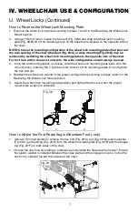
2. Using a 10mm wrench, loosen the hex bolt (Fig. 28:A) and slide the wheel lock mounting
plate (Fig. 28:B) off of the mounting block on the base frame. Repeat on the opposite side of
the chair.
NOTE: Choose the mounting configuration of the wheel lock mounting plates that best suit
the axle spacing of the chair. Standard (Fig. 28:C) or wide mounting (Fig. 28:D) may be
achieved by switching the wheel lock mounting plates to the opposite side of the chair.
For foot lock and/or dual post armrests, the wide configuration should always be used.
3. Once the width configuration is chosen, slide the wheel lock mounting plate back onto the
mount blocks, indexing the T-nuts back into the slot of the mounting plates. Do not tighten
the hex bolt yet.
4. Reattach the wheel lock mounts in the proper configuration according to steps 4 and 5 in the
Reversing the Wheel Lock Mount section.
5. Adjust the wheel lock mounting plate position and tighten the hex nut when the proper
mount plate location is achieved.
How to Adjust the Foot Pedal Angle (Attendant Foot Lock)
1. Use two 10mm wrenches to remove the hex bolt (Fig. 29:A), nut (Fig. 29:B), plastic washer
(Fig. 29:C) and bushing (Fig. 29:D) from the wheel lock index plate (Fig. 29:E) and the linkage
rod (Fig. 29:F) on both sides of the chair.
1. Choose the new hole according to preference and reinstall the hardware from step 1. Ensure
the plastic washer is installed between the index plate and the linkage rod. Also, notice the
hex bolt is installed toward the outside of the chair.
C
D
A
B
Fig. 28
A
E
C
D
B
F
Fig. 29

