background image

29

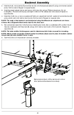
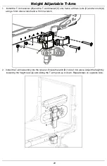
Height Adjustable T-Arm

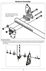
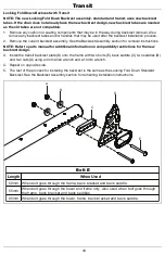
1.   Install the T-Arm receiver (B) and the T-Arm bracket (C) onto frame with two bolts (D) and two nuts (A) 

using a 5mm Allen wrench and a 10mm wrench.

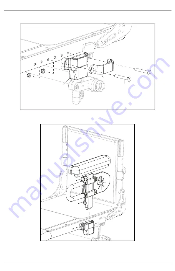
2.   Install the T-Arm assembly into the receiver. Ensure the latch (B) "clicks" into place. Adjust the height by 

loosening the height lever (A) and sliding the T-Arm post up or down. Repeat steps on opposite side.

A

B

C

D

A

B

Summary of Contents for Little Wave XP

Page 1: ...THIS TECHNICAL MANUAL HAS BEEN DEVELOPED FOR AND INTENDED TO BE USED BY A QUALIFIED TECHNICIAN WORKING FOR AN AUTHORIZED KI MOBILITY DEALER...

Page 2: ...tive Technology Practitioner ATP or clinical professional trained to do wheelchair repairs adjustments and retrofits Additional information can be found in the Tsunami and Little Wave Owner Manuals Th...

Page 3: ...le Adj Locking Flip Up Extendable Armrest Available on Little Wave 30 S Swing Away Armrest 31 T Cane and Crutch Holder 32 U Luggage Carrier 33 V Handrim Configurations 34 W Handrim Construction 35 X S...

Page 4: ...ed and that the tool can perform its function properly without damaging any parts or hardware on the chair Tools Needed 2 5mm Allen Wrench Two 8mm Wrenches 3mm Allen Wrench Two 10mm Wrenches 4mm Allen...

Page 5: ...from outside of seat frame to outside of front tube F Front Seat Height see diagram 1 Measured from floor to top of seat tube at front of seat sling G Footrest Width see diagram 1 Measured from inside...

Page 6: ...unt assembly onto the chair frame and secure by installing the four bolts A C D through the caster mount and chair frame holes using a 4mm and a 5mm Allen wrench NOTE There are three different sizes o...

Page 7: ...eel H into fork D with two screws E a threaded barrel F and two spacers G using two 4mm Allen wrenches NOTE There are two sizes of caster stems standard and 3 4 and three sizes of slotted forks short...

Page 8: ...with washer B and nut D using a wrench 2 Install caster wheel G onto fork C with two screws E and the axle shaft F NOTE There are three sizes of caster stems standard 3 4 and 1 that can be used The i...

Page 9: ...8 Caster Forks and Stems Frog Legs Ultra Sport Fork Assembly 1 Install Frog Leg Ultra Sport Fork A onto caster wheel E with axle B screw C and two spacers D using two 4mm Allen wrenches A B C D D E...

Page 10: ...Caster Forks and Stems Frog Legs Phase 2 Carbon Fork Assembly 1 Install Frog Leg Phase 2 Carbon Fork A onto caster wheel E with axle B screw C and two spacers D using two 4mm Allen wrenches A B C D D...

Page 11: ...but no coin is needed 1 Remove the pivot pin screw D using a 4mm Allen wrench 2 Use a punch or small screwdriver and a rubber mallet to push the pivot pin A out 3 Open the fork assembly and remove the...

Page 12: ...t the caster needs to be resquared See instructions below Adjusting the Caster Angle For optimum performance the caster housing should always be at 90 angle to the floor perpendicular to the ground 1...

Page 13: ...be and secure with two bolts B and the set screw C using a 4mm Allen wrench and a 2 5mm Allen wrench 2 Install the camber mount B onto the camber mount clamp and secure with two bolts C two washers D...

Page 14: ...used for mounting the camber mount and the back plate set the seat depth Use the holes that provide the desired seat depth NOTE One long bolt 65mm and one oval top nut are used in the attaching of the...

Page 15: ...A and secure with two bolts B and the set screw C using a 4mm Allen wrench and a 2 5mm Allen wrench 2 Install the camber mount A onto the camber mount clamp and secure with two bolts D and two nuts B...

Page 16: ...used for mounting the camber mount and the back plate set the seat depth Use the holes that provide the desired seat depth NOTE One long bolt 65mm and one oval top nut are used in the attaching of the...

Page 17: ...1 Install the tower clamps B C onto the frame with the camber mount tube E and the camber tube cap F using two screws A and two nuts D with a 4mm Allen wrench 2 Install the camber tube mounting clamp...

Page 18: ...nstall camber tube D into the camber tube mounting clamp and secure with screw B and nut C using a 4mm Allen wrench and an 8mm wrench Install and tighten the two set screws A with a 2 5mm Allen wrench...

Page 19: ...r axle receiver nut axle plate washer and camber adapter into the camber tube NOTE The camber adapter is available with 0 2 4 6 and 8 camber 2 Secure the camber adapter into the camber tube with two s...

Page 20: ...lightens the front end making your chair more maneuverable Moving the camber mounts rearward makes the chair more stable and less likely to tip over rearward 1 To adjust the center of gravity locatio...

Page 21: ...crews A 2 per side that secure the camber tube clamp 2 Rotate the camber tube B until the screws C that secure the camber spuds are level with the ground The toe is now set at zero 3 Before tightening...

Page 22: ...krest latch strike bushing I and a nut A onto the frame and in the backrest latch so it catches See table below for bolt sizes 4 Repeat steps on opposite side NOTE The seat depth is determined by the...

Page 23: ...marked in the same sequence as the column headers in the table Stackup Nut Tower Tube Nut Tower Tube Large Saddle Bracket Nut Tube Large Saddle Bracket Nut Small Saddle Tube Large Saddle Bracket Total...

Page 24: ...est tubes and securing with bolt E back plate D two saddles C washer B and nut A using a 5mm Allen wrench and an 8mm wrench Repeat on opposite side A B C D E F G H I J K L M N O P A B C D E A B C D E...

Page 25: ...angle of the backrest can be adjusted using the different arc adjustment cam holes Choose the configuration that works best for the chair user 5 Secure backrest assembly to the frame by installing tw...

Page 26: ...E screws C threaded barrels D and the upper back tube assembly A using two 3mm Allen wrenches NOTE The straight upper back standard push handle and fold down push handle upper backs are shown in the i...

Page 27: ...NOTE The fixed height back post standard push handle and fold down push handle upper backs are shown in the image below The standard push handle and fold down push handle upper backs also require sle...

Page 28: ...h NOTE The detent button on the bottom of the back post will click into place when properly installed Ergo Stroller Handle 1 Install the ergo stroller handle clamp F H onto the middle of the rigidizer...

Page 29: ...ar and secure with two screws A and two nuts D using a 5mm Allen wrench NOTE The clamps can be installed onto the rigidizer bar in the straight or angled orientation See image below for details 2 Repe...

Page 30: ...e with two bolts D and two nuts A using a 5mm Allen wrench and a 10mm wrench 2 Install the T Arm assembly into the receiver Ensure the latch B clicks into place Adjust the height by loosening the heig...

Page 31: ...back of the chair Slide the armrest to desired length available by the predrilled holes and reinstall the screw and bolts 3 Set the height of the armrest There are four holes on the armrest that allo...

Page 32: ...ng the receiver can be skipped because the receiver and mount are one piece The Tsunami ALX version is not angle adjustable 2 Install the swing away receiver F onto the swing away arm mount with three...

Page 33: ...n wrench and an 8mm wrench 2 Install the crutch holder tube assembly onto the camber tube with the clamps D E and two bolts C using a 5mm Allen wrench 3 Install the crutch holder velcro strap A onto t...

Page 34: ...he frame or footrest tubes 1 Install luggage carrier fork F and clamp B by installing two screws E and barrel nut D through the clamp and fork using two 4mm Allen wrenches 2 Secure the clamp in the de...

Page 35: ...101160 101197 101160 101091 101464 101460 20 5 Spoke X Core 101961 5 Aluminum Projection Natural Fit 100629 Plastic Coated 101756 100724 101897 101963 22 5 Spoke X Core 101962 101898 101964 24 5 Spok...

Page 36: ...sequencing of hardware for the three styles of handrims is shown below The specific hardware used is determined in the chart on the previous page based on the tire and handrim being used Spacer Style...

Page 37: ...pe onto the seat as shown in the image below The AB Tape should cover as much area as possible without hanging over the edge or covering one of the screw holes Part Number AB Tape Size Seat Pan Depth...

Page 38: ...ry C Repeat on opposite side The seat rail is shown outside of the sleeve to show the hole alignment in the image below 2 Secure the seat rail and seat upholstery onto the chair frame with screws A us...

Page 39: ...post C with two screws A using a 4mm Allen wrench On the opposite side install the side guard post stop B with a screw A using a 4mm Allen wrench NOTE Do not overtighten the post stop B Overtightenin...

Page 40: ...ost stop B with a screw A using a 4mm Allen wrench NOTE Do not overtighten the post stop B Overtightening will flare the vertical sides outward which will prevent the post stop from functioning proper...

Page 41: ...of the post can also be adjusted later if needed NOTE It is possible to install the post stop B in a hole high enough that it will not mate to the receiver Ensure fit after installment before using t...

Page 42: ...lts from the post mount with a 3mm Allen wrench 2 Rotate the fender either way to align the fender with the profile of the tire 3 Rotate the post mount plate so the four holes align with the desired h...

Page 43: ...o nuts A using a 4mm Allen wrench and a 10mm wrench 2 Repeat steps on opposite side Backrest is installed as shown in Backrest Assembly section Caster Mount Transit Bracket 1 Install the caster mount...

Page 44: ...er to parts manual for additional information on compatibility restrictions for the new backrest design 3 Install the transit backrest plate D onto the frame with two bolts E back saddle C two saddles...

Page 45: ...ing off of the tape and snap footrest protectors onto the footrest as seen below Apply tape to the inside of the footrest protectors Snap the footrest protectors onto the footrest Footplate Width Part...

Page 46: ...e offset are shown below The installation process is the same for both footrest tubes 2 Install two screws C into the footrest flip stop clamp to secure the footrest tubes using a 5mm Allen wrench Ins...

Page 47: ...tall the footrest platform B onto the footrest adjustable clamp and secure with two screws A and two nuts D using a 5mm Allen wrench 2 Install the two clamps C D one end on the footplate riser tube an...

Page 48: ...rews F and two nuts I using a 5mm Allen wrench Install the footplate risers D onto the footrest tubes with screws A and saddles C using a 4mm Allen wrench Install plugs B into the end of the footrest...

Page 49: ...e by installing the footrest platform D onto the clamp with two screws C and two nuts F using a 5mm Allen wrench Install the plugs A into the ends of the footrest tubes 2 Install the two clamps A B on...

Page 50: ...tall foot platform C onto pivots with two screws B using a 5mm Allen wrench While installing the foot platform slide the flip foot strap A onto frame tube 5 Install the top and bottom footplate clamps...

Page 51: ...els B using two 4mm Allen wrenches to remove the frame connector Swap in the new frame connector and reinstall hardware to secure NOTE Other parts and assemblies on the chair need to checked and or ad...

Page 52: ...heels B onto the anti tip tube with a bolt C and nut A using two 10mm wrenches Little Wave Anti Tip Receiver 1 Install the anti tip receiver B onto the camber tube mounting clamp with two screws A and...

Page 53: ...p receiver C onto the camber tube and secure with two screws A and a threaded barrel B using two 4mm Allen wrenches Repeat on opposite side 2 Install the anti tip assembly D into receiver until detent...

Page 54: ...5th Wheel 1 Assemble the 5th wheel arm mount as shown below using two wrenches 2 Install the caster D into the 5th wheel mount forks with two screws A threaded barrel B and two caster spacers C using...

Page 55: ...crews on the camber tube C will also need to be removed to clear the clamps using a 4mm Allen wrench NOTE If you are retrofitting to the standard 5th wheel remove the camber tube completely because a...

Page 56: ...h Wheel 5 Center the 5th wheel mounting clamp and secure in place by installing three screws A B using a 4mm Allen wrench Install the 5th wheel into the clamp and ensure the detent buttons click or lo...

Page 57: ...is on the next page The Under Seat Scissor Lock always comes assembled so it is not shown below Push to Lock Flush Mount Short Thro Scissor Locks Low Profile Scissor Lock Extension Bar Assembled View...

Page 58: ...chair frame in position using a 5mm Allen wrench and a 6mm Allen wrench Once installed ensure wheel lock engages at least 1 8 into tire and locks properly prevent the chair from moving when engaged N...

Page 59: ...Ki Mobility 5201 Woodward Drive Stevens Point Wisconsin 54481 715 254 0991 www kimobility com DCN0486 0...

Reviews: