background image

6. Setup

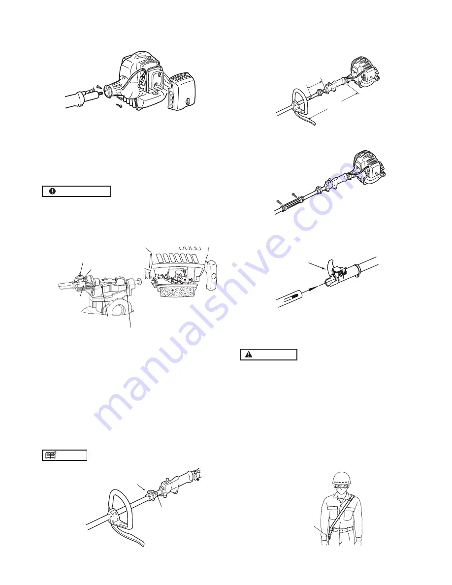
Insert the cable

to the end of

adjuster

Full on stopper

Idling adjust screw

M3 screw

Adjuster

MOUNTING ENGINE

1.

2.

3.


IMPORTANT

Tighten the screws gradually.

CONNECTING THROTTLE WIRE

1. Remove the air filter cover.

2. Connect the end of the throttle wire to the joint on the

top of the carburetor.

3. Connect throttle wire with carburetor. Insert the cable

to the end of adjuster fix the throttle cable by tighten-

ing M3 screw. (Tightening torque: 0.4 ~ 0.8 N.m.)

4. Make sure the ‘STOPPER-PLATE’ of carburetor moves

to contact with ‘IDLING ADJUST SCREW’ and the

‘SWING-ARM’ of carburetor moves to contact with

‘FULL ON STOPPER’ by gripping throttle lever.

CONNECTING SWITCH WIRES

• Connect the switch wires between the engine and the

main unit. Pair the wires of the same colour.

SUSPENSION POINT


NOTE

Shoulder harness goes on this point

Mount the handle to the shaft tube and suspension point

at a location that is comfortable for you.

MIN

SPA

CING

About 19 inches (48 cm)

INSTALLING HANDLE

arrow mark

SUSPENSION POINT

8

JOINT ATTACHMENT

Insert the attachment to the main shaft.

Tighten the knob bolt securely

.

Knob bolt

Push the shaft tube towards the clutch housing and 

rotate the drive by hand to check that it is engaged 

with the gears.

Insert the shaft tube into the clutch housing and align 

the positioning hole on the clutch housing and the 

shaft tube.  Install the screw.

Fasten the clamp securely with two screws.

Install  the  shaft  grip  to  the  shaft  tube  and  clamp 

down at a position most suitable for you.

HARNESS


WARNING

ALWAYS WEAR THE PROVIDED HARNESS WHEN 

USING THE MACHINE!

Always make sure the machine is hooked 

securely to the harness.  If you don’t, you will not 

be able to control the machine safely.  This may 

result in injury to yourself and/or others.  Never 

use a harness with a defective quick release or 

any other damage.

HOW TO WEAR HARNESS

1.

                   (1) Hanger

Wear the provided harness with the hanger on 

your right side.

Summary of Contents for Sherwood 52

Page 1: ...Hedge Trimmer Pruner Instructions Manual Read instructions manual before use Equipmart Ltd Kiam House Birchill Road Knowsley Ind Park North Merseyside L33 7TD United Kingdom T 0044 151 548 5500 F 004...

Page 2: ...s instructions which must be followed in order to prevent accidents that could lead to serious bodily injury or death This mark indicates instructions which must be followed to prevent any mechanical...

Page 3: ...11dB A K 3dB A Vibration level max idling running 5 11m s 9 66m s K 1 5m s Dry weight approx 5 2kg Blade rotation direction Counterclockwise from operator s view Cutting device Metal blade 3 teeth Nyl...

Page 4: ...d eye and ear protection 3 Wear foot protection 4 Wear gloves 5 Beware of thrown objects 6 Warning Attention 7 Keep all people 15 meters away from the machine 4 Symbols on the machine For safe operati...

Page 5: ...y see a doc tor before getting worse 2 To avoid noise complaints in gen eral operate product between 8 a m and 5 p m on weekdays and 9 a m to 5 p m on weekends 1 2 Keep this manual handy so that you m...

Page 6: ...in the manual 1 Grip the handles rmly with both hands using your whole hand Place your feet slightly apart slightly further apart than the width of your shoulders so that your weight is distributed ev...

Page 7: ...pera tion or the product becoming un able to operate properly HANDLING FUEL 1 2 Never smoke while operating the unit or re lling its fuel tank 3 When re lling the tank always turn off the engine and a...

Page 8: ...e operation 7 Kickback may occur when the nose or tip of the guide bar touches an object or when the wood closes in and pinches the pruner in the cut Contact with the tip may in some cases cause a sud...

Page 9: ...and suspension point at a location that is comfortable for you MIN SPACING About 19 inches 48 cm INSTALLING HANDLE arrow mark SUSPENSION POINT 8 JOINT ATTACHMENT Insert the attachment to the main sha...

Page 10: ...haft Remove the screw from the end of the transmission Insert the end of the gear case into the drive shaft Line up the hole on the end of the transmission with the hole on the drive shaft and screw i...

Page 11: ...orrect tension Check chain tension regularly especially with a new chain as it should expand after first use Depending on your working posture slide the harness suspension point up down the main shaft...

Page 12: ...r for the sake of your health and the environment Poor quality petrol or oils may damage sealing rings fuel lines or fuel tank of the engine Measure out the quantities of petrol and oil to be mixed Pu...

Page 13: ...rted When start ing the engine place the product onto the ground in a flat and clear area holding it firmly in place to ensure neither the cutting part nor the throttle comes into contact with any obj...

Page 14: ...o cut heavy growth The rate of the cutting motion will depend on the material being cut Heavy growth will require slower move ments than light growth Never swing the unit quickly roughly as you will b...

Page 15: ...e cuts too deep into weeds Adjust the engine speed and cutting depth according to the condition of the object 2 3 Rotating parts that are fitting incorrectly may cause serious accidents and or serious...

Page 16: ...e trimmer The oil reservoir has a capacity sufficient to provide about 40 minutes of cutting time when set to deliver the minimum flow rate Be sure to refill the oil tank every time you refuel the pet...

Page 17: ...vice to the machine Con tact with moving parts or hot exhaust may result in personal injury The air lter if clogged will reduce engine perfor mance Check and clean the lter element in warm soapy water...

Page 18: ...at the spring and the washers are in place 6 While holding the spool against the housing pull the line ends to release them from the slot 7 Line up the slot on the bottom cap with the hook on the hous...

Page 19: ...rease fitting Screwing in the screw too tightly may make it impossi ble for the blades to move while not screwing in the screw tightly enough may make the blades of the trimmer feel dull and cause lea...

Page 20: ...chain link has been set check the depth gauge and le it to the correct level as illustrated Make sure every chain link has the same length and edge angles as illustrated 4 Cutter length 5 Filing angle...

Page 21: ...e starts but does not keep running hard re starting CHECK PROBABLE CAUSES ACTION fuel tank incorrect fuel or staled fuel drain it and use correct fuel carburetor adjustment screw out of normal range a...

Page 22: ...luded when returning to Kiam Power Products Kiam House Birchill Road Knowsley Ind Park North Merseyside L33 7TD United Kingdom Kiam Power Products Return Sheet Name ___________________________________...

Reviews: