background image

SAFETY FIRST


WARNINGS IN THE MANUAL

WARNING

IMPORTANT

NOTE

1

Contents

Instructions  will contain warnings within this manual, they will be marked with a     symbol concern-

ing critical points which must be taken into consideration to prevent any possible serious bodily 

injury.  You are requested to read all such instructions carefully and follow them without fail.

This mark indicates instructions which must be followed in order to prevent accidents that could lead to serious 

bodily injury or death.

This mark indicates instructions which must be followed to prevent any mechanical failures, breakdowns and/or 

damage.

This mark indicates hints or directions that are useful in the use of this machine.

1.
2.
3.
4.
5.
6.
7.
8.
9.

10.
11.
12.
13.
14.

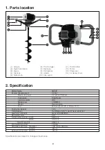
Parts location ............................................................................
Specifications ...........................................................................
Warning labels on the machine ................................................
Symbols on the machine ..........................................................
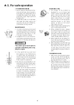
For safe operation .....................................................................
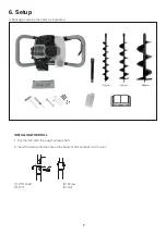
Setup ........................................................................................
Fuel ...........................................................................................
Operation ..................................................................................
Maintenance .............................................................................
Storage .....................................................................................
Troubleshooting guide ..............................................................
Disposal ....................................................................................
Spare parts ...............................................................................
Warranty ...................................................................................

2
2
3
3
4
7
8
9
10
11
12
12
12
13

Summary of Contents for Sherwood KA500

Page 1: ...ol Earth Auger Instructions Manual Read instructions manual before use Equipmart Ltd Kiam House Birchill Road Knowsley Ind Park North Merseyside L33 7TD United Kingdom T 0044 151 548 5500 F 0044 151 5...

Page 2: ...instructions which must be followed in order to prevent accidents that could lead to serious bodily injury or death This mark indicates instructions which must be followed to prevent any mechanical f...

Page 3: ...ture Petrol 25 2 Stroke Oil 1 Adaptable drill size Diameter 100 mm to 200 mm Model Name KA500 Engine Displacement 3 52 cm Maximum power 2 2 kW at 7500rpm m g a r h p a i D Ignition system CDI Spark pl...

Page 4: ...or if you don t ob serve the proper usage written in the manual 4 Symbols on the machine For safe operation and maintenance symbols are carved in relief on the machine According to these indications...

Page 5: ...ody see a doc tor before getting worse 2 To avoid noise complaints in gen eral operate product between 8 a m and 5 p m on weekdays and 9 a m to 5 p m on weekends 1 THIS MACHINE CAN CAUSE SERIOUS INJUR...

Page 6: ...re to maintain a steady even posture while working 2 Maintain the speed of the engine at the level required to perform drilling work and never raise the speed of the engine above the necessarylevel 3...

Page 7: ...ling its fuel tank 3 When re lling the tank always turn off the engine and allow it to cool down Take a careful look around to make sure that there are no sparks or open ames any where nearby before r...

Page 8: ...ains the items as illustrated 7 INSTALLING THE DRILL 1 Put the drill onto the auger output shaft 2 Insert the screw into the hole on the head of drill 1 PTO shaft 2 Drill 3 Screw 4 Nut 1 2 3 4 and loc...

Page 9: ...r for the sake of your health and the environment Poor quality petrol or oils may damage sealing rings fuel lines or fuel tank of the engine Measure out the quantities of petrol and oil to be mixed Pu...

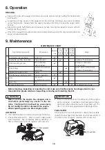
Page 10: ...screw up 1 3 2 ADJUSTING IDLING SPEED 1 When the engine tends to stop frequently at idling mode turn Idle speed adjuster clockwise 2 When the cutting head keeps rotating after releasing the trigger t...

Page 11: ...i t s u j d a e e s idle adjusting screw idling speed if necessary m m 5 6 0 n i 6 2 0 P A G t s u j d a e r d n a n a e l c spark plug plug gap replace if necessary intake air cooling vent clean thr...

Page 12: ...arter turn with socket wrench Inspect the exhaust regularly for loose fasteners damage or corrosion If any sign of exhaust leak age is found stop using the machine and have it repaired immediately Not...

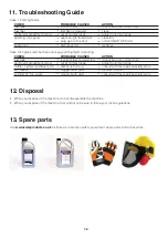
Page 13: ...fouled wet clean dry plug gap is incorrect correct GAP 0 65 mm spark plug disconnected retighten Case 2 Engine starts but does not keep running hard re starting CHECK PROBABLE CAUSES ACTION fuel tank...

Page 14: ...luded when returning to Kiam Power Products Kiam House Birchill Road Knowsley Ind Park North Merseyside L33 7TD United Kingdom Kiam Power Products Return Sheet Name ___________________________________...

Reviews: