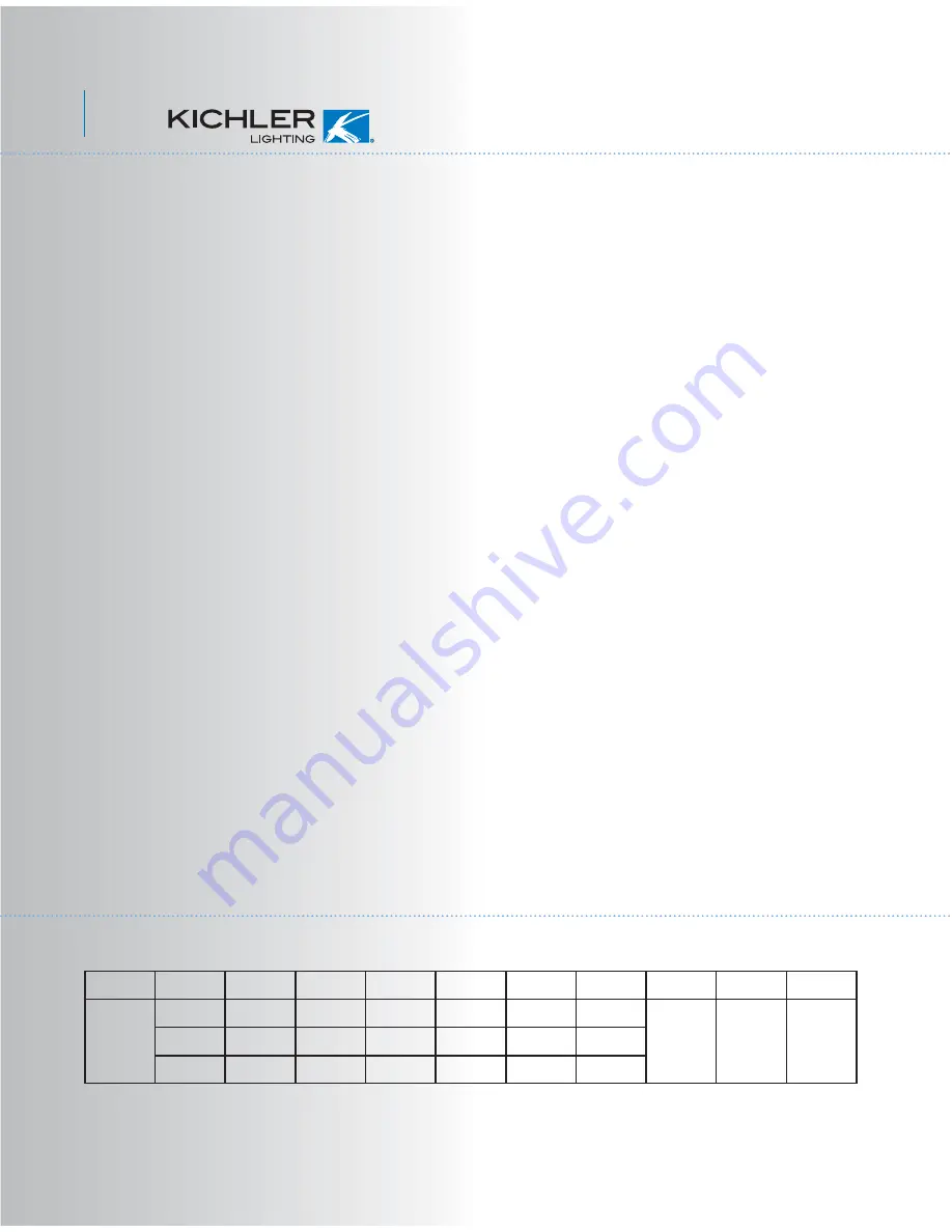
background image

15. SPECIFICATIONS

2.0'

27.50

kgs

29.70

kgs

0.40

0.35

0.21

53.00

31.00

11.00

174

130

71

4543.64

3421.16

1823.13

RPM

CFM

85.73

110.36

165.74

CFM/W

N.W.

G.W.

C.F.

120

120

120

Fan Size 

52"

Speed Volts  Amps Watts

High

Medium

Low

These are approximate measures. They do not include Amps and Wattage used by the light kit.

14. TROUBLESHOOTING

11

Problem

Fan will not start.

Fan sounds noisy.

Fan wobble.

Solution

1. Check that all fuses or circuit breakers are installed or in the ON position.
2. Check all electrical connections to insure proper contact. 

CAUTION:

 Make 

sure the main power is OFF when checking any electrical connection.

1. Make sure all motor housing screws are snug.
2. Make sure the screws that attach the fan blade bracket to the motor hub is 
tight.
3. Make sure wire nut connections are not rubbing against each other or the 
interior wall of the switch housing.

CAUTION:

 Make sure main power is off.

4. Allow a 24-hour "breaking-in" period. Most noise associated with a new fan 
disappear during this time.
5. If using an optional light kit, make sure the screws securing the glassware 
are tight. Make sure the light bulbs are not touching any other component.
6. Some fan motors are sensitive to signals from solid-state variable speed 
controls. If you have installed this type of control, choose and install another 
type of control.
7. Make sure the upper canopy is a short distance from the ceiling. It should not 
touch the ceiling.

1. Check that all blade and blade arm screws are secure.
2. Most fan wobbling problems are caused when blade levels are unequal. 
Check this level by selecting a point on the ceiling above the tip of one of the 
blades. Measure this distance. Rotate the fan until the next blade is positioned 
for measurement. Repeat for each blade. The distance deviation should be 
equal within 1/8".
3. Use the enclosed Blade Balancing Kit if the blade wobble is still noticeable.
4. If the blade wobble is still noticeable, interchanging two adjacent (side by 
side) blades can redistribute the weight and possibly result in smoother 
operation.

WARNING:

 TO REDUCE THE RISK OF PERSONAL INJURY, DO NOT BEND 

THE BLADE ARMS WHILE INSTALLING, BALANCING OR CLEANING THE 
FAN.  DO NOT INSERT FOREIGN OBJECTS BETWEEN ROTATING FAN 
BLADES.

Summary of Contents for Bronson

Page 1: ...chler Lighting 7711 East Pleasant Valley Road P O Box 318010 Cleveland Ohio 44131 8010 Customer Service 866 558 5706 8 30 AM to 5 00 PM EST Monday Friday Instruction Manual Bronson A Kichler Select ceiling fan ...

Page 2: ...gents when cleaning the fan or fan blades A dry dust cloth or lightly dampened cloth will be suitable for most cleaning 11 After making the electrical connections spliced conductors should be turned upward and pushed carefully up into outlet box The wires should be spread apart with the ground wire and white common wire to one side with the black load wire to the other side of the outlet box 12 El...

Page 3: ... shade j 40W B8 candelabra bulbs 3 k Part bag contents 1 Mounting hardware wood screw flat washer spring washer star washers 2 wire nuts 3 machine screws 2 washers 2 screws 2 2 Blade attachment hardware screws 14 washers 14 fiber washers 14 3 Safety cable hardware wood screw lock washer flat washer 4 Pull chains and fobs 2 5 Balance Kit Philips screw driver Blade screw driver 11 mm wrench Step lad...

Page 4: ...mples of different ways to mount the outlet box NOTE If you are installing the ceiling fan on a sloped vaulted ceiling you may need a longer downrod to maintain proper clearance between the tip of the blade and the ceiling A minimum clearance of 12 is suggested for optimal operation NOTE Depending on the location you have selected for installation you may need to purchase and install a Joist Hange...

Page 5: ...ottom of the ceiling mounting bracket Turn the canopy counterclockwise and remove Fig 5 Step 3 Pass the 120 volt supply wires from the ceiling outlet box through the center of the ceiling mounting bracket Fig 6 Step 4 Attach the ceiling mounting bracket to the outlet box using the screws and washers included with the outlet box Fig 6 Step 5 Remove the hanger ball from the downrod assembly by loose...

Page 6: ...assembly into position and place the hanger ball into the ceiling mounting bracket Rotate the entire assembly until the Check Tab has dropped into the Registration Slot and seats firmly Fig 10 The entire motor assembly should not rotate left or right when seated properly WARNING Failure to properly seat the Check Tab can damage the ceiling fan during operation Hanger ball Downrod Canopy cover Cano...

Page 7: ...d off the power at the main circuit panel Follow the steps below to connect the fan to your household wiring Use the wire connecting nuts suppled with your fan Secure the connectors with electrical tape Make sure there are no loose wire strands or connections Step 1 Connect the fan supply black wire and light supply blue wire to the black household supply wire as shown in Figure 12 Step 2 Connect ...

Page 8: ...opy Canopy cover Screws 9 ATTACHING THE FAN BLADES Fig 14 CAUTION Remove the five rubber shipping blocks attached to the face of the motor These blocks keep the motor from shifting during shipping and MUST be removed during installation Step 1 Attach a blade to a blade bracket using the screws metal washers and fiber washers provided Fig 14 Make sure the blade is straight when set on the blade bra...

Page 9: ...ach the light kit assembly to the mounting plate with the three screws provided Make use each screw is tight Fig 16 1 Loosen the two screws on the mounting ring attached to the motor shaft and remove and save the third screw Fig 15 2 Place the key holes on the mounting plate over the 2 screws previously loosened from the mounting ring turn mounting plate until it locks in place at the narrow secti...

Page 10: ...he decorative cap onto the light kit stem Feed the beaded pull chain from the light kit stem through the hold in the decorative nut and thread the decorative nut on securely DO NOT OVER TIGHTEN 4 Attache one pull chain fob to each of the beaded pull chains Fig 17 Note Make sure to leave enough space between the fan pull chain and the bulbs so the chain doesn t rub against any of the bulbs Decorati...

Page 11: ...ack Slide Switch on the side of the switch housing controls the direction of the blades Forward and Reverse Warm weather Forward counter clockwise A downward airflow creates a cooling effect as shown in Fig 18 This allows you to set your air conditioner on a warmer setting without affecting your comfort Cool weather Reverse clockwise An upward airflow moves warm air off the ceiling area as shown i...

Page 12: ...ing an optional light kit make sure the screws securing the glassware are tight Make sure the light bulbs are not touching any other component 6 Some fan motors are sensitive to signals from solid state variable speed controls If you have installed this type of control choose and install another type of control 7 Make sure the upper canopy is a short distance from the ceiling It should not touch t...

Reviews: