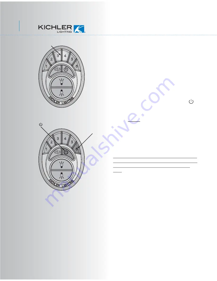
background image

11

Fig. 21

Fig. 22

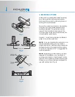
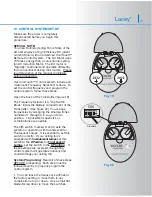
2.  Insert both batteries and make sure they 
are seated correctly in each recess with the 
Po sign facing up.  Replace the battery 
cover.  (Figure 20)

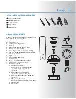
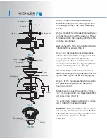
3.  Test the transmitter by pushing and 
releasing ANY button briefly.  A Blue Light 
should illuminate under the 3-4 buttons. (Fig. 
21) If not, check to make sure the batteries 
are inserted and seated correctly.

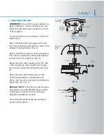
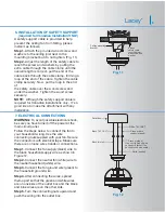
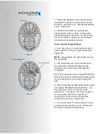
Power Up and Programming:

4.  Turn the power on, press and hold the 
button until the ceiling fan light blinks twice  
(Figure 22)

NOTE:


Do not

 press any other button during 

this procedure.

5.  The transmitter just communicated with 
the ceiling fan, selected the appropriate 
frequency, did a self check and signaled 
“complete”.

NOTE:  This operation must be started WITHIN the 
first 120 seconds (2 minutes) of turning the power 
on.  No other buttons can be push during this 
time.

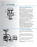
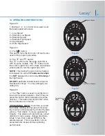
6.  After the ceiling fan light blinks twice, press 
and release the High Speed (6) Button.  Let 
the ceiling fan run for a minimum of 90 
seconds ( 1 ½ minutes).  The control system 
will do another self check, initialize all 
operational functions and complete the 
programming process  (Figure 23).

7.  Your CoolTouch™ Control System is now 
programmed and ready for use.  Please see 
the follow Operational Instructions.

Blue Light

#1  Press/hold      Button

#2  Press 6 Button

Summary of Contents for Lacey

Page 1: ... Friday Instruction Manual Lacey TM A Kichler Décor ceiling fan Designed to coordinate with a popular Kichler Lighting collection Includes our new CoolTouchTM 6 Speed DC Control System Looks permanent but goes wherever you go U S Patent Pending Our High Efficiency DC Motor Technology Requires 70 Less energy than a Standard Ceiling Fan AC Induction Motor ...

Page 2: ...ton while the fan is running 8 Avoid placing objects in the path of the blades 9 To avoid personal injury or damage to the fan and other items be cautious when working around or cleaning the fan 10 Do not use water or detergents when cleaning the fan or fan blades A dry dust cloth or lightly dampened cloth will be suitable for most cleaning 11 After making the electrical connections spliced conduc...

Page 3: ...st assembly j Glass shade k 22W T9 circular fluorescent lamp l CoolTouch Control System m Part bag contents 1 Mounting hardware wood screws 2 flat washers 2 star washers 2 wire nuts 3 screws 2 2 Blade attachment hardware screws 17 fiber washers 17 3 Blade bracket attachment hardware screws 12 4 Safety cable hardware wood screw spring washer flat washer 5 Allen wrench 6 Balance Kit Philips screw dr...

Page 4: ...support must be able to fully support the moving weight of the fan at least 50 lbs Do not use plastic outlet boxes Figures 1 2 and 3 are examples of different ways to mount the outlet box NOTE If you are installing the ceiling fan on a sloped vaulted ceiling you may need a longer downrod to maintain proper clearance between the tip of the blade and the ceiling A minimum clearance of 12 is suggeste...

Page 5: ...ceiling mounting bracket to the outlet box using the screws and washers included with the outlet box Fig 5 Step 3 Remove the coupling cover from the motor housing by removing the four screws from the four decorative arched braces Fig 6 Step 4 Remove the hanger ball from the downrod assembly by loosening the set screw removing the cross pin and sliding the ball off the rod Fig 7 SPECIAL NOTE For pr...

Page 6: ...rews previously removed Fig 9 Thread the hanger ball onto the downrod insert the cross pin through the downrod and tighten Now tighten the set screw Fig 9 Step 8 Lift the motor assembly into position and place the hanger ball into the ceiling mounting bracket Rotate the entire assembly until the Check Tab has dropped into the Registration Slot and seats firmly Fig 10 The entire motor assembly shou...

Page 7: ... Canadian installations only It s a good idea to make the attachment with any installation WARNING To avoid possible electrical shock be sure you have turned off the power at the main circuit panel Follow the steps below to connect the fan to your household wiring Use the wire connecting nuts suppled with your fan Secure the connectors with electrical tape Make sure there are no loose wire strands...

Page 8: ...over are snug Fig 13 Warning Make sure the Check Tab at the bottom of the hanger bracket is properly seated in the Registration Slot on the side of the hanger ball before attaching the canopy to the bracket Failure to properly seat the Check Tab could damage the electrical wires when to ceiling fan blade direction is changed while the fan is running 8 FINISHING THE INSTALLATION 9 ATTACHING THE FAN...

Page 9: ...Turning the power off using a wall switch is not sufficient to prevent electrical shock Step 1 Loosen two of the mounting screws on the Light Fixture Plate and remove the third Fig 16 Step 2 Hold the Lamp Ballast Assembly close to the light fixture and connect the white wires from the Ballast and the fan by pushing the connectors together Follow the same procedure with the black wires Fig 16 Step ...

Page 10: ...enlarges the holder allowing the lamp to pop into place easier Fig 17 Connect the Lamp Ballast to the Lamp by pushing the Four Pin Connector into the receptacle on the Lamp Step 2 Remove the decorative nut glass cap and metal nut from the lamp ballast stem Place the glass shade over the lamp ballast stem and secure the shade with a metal nut rubber side touching the shade Fig 18 Step 3 Fit the dec...

Page 11: ...tery compartment of the Transmitter See figure 20 You change frequencies by arranging the small switches numbered 1 through 4 in a up or down position 16 possible frequencies or combinations are possible The fifth switch marked D and X sets the system for operation with Incandescent or Fluorescent Lamps It is essential to set this switch correctly If your ceiling fan is equipped with Incandescent ...

Page 12: ... this procedure 5 The transmitter just communicated with the ceiling fan selected the appropriate frequency did a self check and signaled complete NOTE This operation must be started WITHIN the first 120 seconds 2 minutes of turning the power on No other buttons can be push during this time 6 After the ceiling fan light blinks twice press and release the High Speed 6 Button Let the ceiling fan run...

Page 13: ...t fixture DO NOT substitute incandescent Lamps for Fluorescent Lamps You may damage your ceiling fan Figure 25 4 The button is used to set the fan in forward or reverse operation Each time you press this button the fan blades will reverse direction This button functions ONLY when the fan blades are in motion OPERATIONAL NOTE Each time you start the blades rotating at any speed or reverse the direc...

Page 14: ... under System Programming Speed settings for warm or cool weather depend on factors such as the room size Ceiling height number of fans and so on Warm Weather Operation Forward counter clockwise A downward airflow creates a cooling effect as shown in Fig 26 This allows you to set your air conditioner on a warmer setting without affecting your general comfort Cool Weather Operation Reverse clockwis...

Page 15: ...lTouch Control System Transmitter You can replace an existing wall switch or install the transmitter on ANY flat surface Option 1 Install the control system using an existing wall switch outlet box Make sure the electrical power is TURNED OFF at the main panel before continuing Step 1 Remove the existing wall plate and the old switch from the wall outlet box Wire nut the BLACK leads hot together a...

Page 16: ...stance from the ceiling It should not touch the ceiling 1 Check that all blade and blade arm screws are secure 2 Most fan wobbling problems are caused when blade levels are unequal Check this level by selecting a point on the ceiling above the tip of one of the blades Measure this distance Rotate the fan until the next blade is positioned for measurement Repeat for each blade The distance deviatio...

Reviews: