TM0064
Page 38 of 91
Issue 2.01
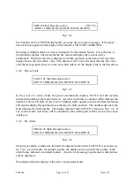
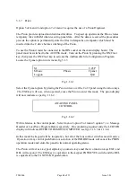
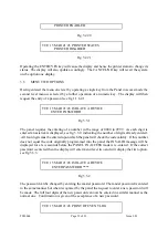
Should a system alarm fault, i.e. caused by either a sounder wiring fault, of by a manual
isolation of the auxiliary output the display format of the LCD/VFD is as shown on fig 1.4.10.
This is accompanied by the illumination of the EXTERNAL FAULT and SYSTEM FAULT
LEDs and activation of the internal buzzer.
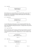
2.4.10 Supply Fault
SYSTEM FAULT 01
SUPPLY FAULT
Fig 1.4.11
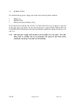
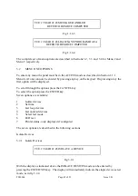
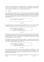
Should a supply fault occur the display format of the LCD/VFD is as shown on fig 1.4.11.
The SYSTEM FAULT LED is illuminated, the SUPPLY HEALTHY LED extinguished and
the internal buzzer sounded. The power supply unit is fitted with various LEDs to high light
the actual supply fault.
2.4.11 Alarms Sounded
TUE 15 MAR 21:45
ALARMS SOUNDED
Fig 1.4.12
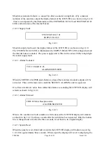
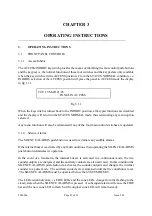
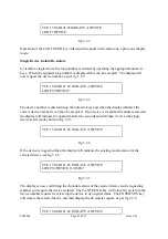
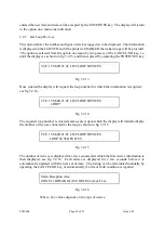
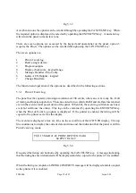
When the SOUND ALARMS push-button is pressed the monitored sounder outputs will be
activated. These will remain active until the SILENCE ALARMS switch is operated.
If no fires or faults are active then whilst the alarms are sounding the LCD/VFD display will
remain as shown in fig 1.4.12.
2.4.12 Alarms Silenced
FIRE 01 Main Reception Area
ALARMS SILENCED
Fig 1.4.13
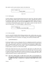
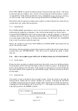
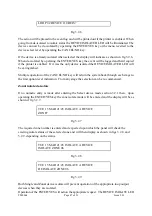
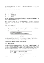
When a fire condition or fault condition is first silenced the LCD/VFD display will indicate
as shown in fig 1.4.13 for three seconds after the switch has been operated. Only the bottom
line is changed and will, after the three seconds, revert back to its original display.
2.4.13 System Reset
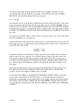
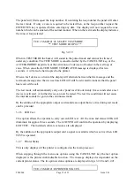
When the panel is reset (from fault or alarm) the LCD/VFD display will indicate as per fig
1.4.14 for approximately three seconds. Where upon the display will revert to displaying the

