background image

TM0064

Page 79 of 91

Issue 2.01

3.

If all is correct the VFD will display: LOGGING DEVICES.

If any faults are found the panel will record a system fault, light the appropriate LEDs and
display an appropriate ERROR MESSAGE. It is possible that the yellow fault lights inside
the panel are illuminated.

NOTE THE STATUS OF THE PANEL IN FAULT CONDITION

Switch the panel off:

1.

Disconnect the batteries.

2.

Disconnect the a.c. mains.

3.

Refer to Fault Diagnosis Chart in the Section 4.3 Maintenance before proceeding. 

Assuming that all is well, you can test the internal voltages as described in the 
following sections.

4.9.3 Testing Loops of Detectors

This test is to check the state of the loops and detectors.

1.

Disconnect the power to the panel.

2.

Remove the links from the loop 1 terminals on the terminal board and insert the loop 
connections observing the polarity (+ and -).

3.

Power the panel back up.

4.

If the yellow fault light on the terminal board remains on after power up, switch the 
panel off  and check the loop for continuity (+ to +) and (- to -). Check for a short 
circuit b and -.

5.

If the loop is healthy, i.e. no fault light on the terminal board, wait until the
LOGGING DEVICES message is replaced with the date on the display.

6.

Select List Loop Devices via the keypad. The VFD will then prompt you with LOOP 
?. Refer to the Section 3 Operating Instructions.

Assuming that all is correct, repeat this procedure with the next loop.

The above listings can be verified against as Installed Drawings, programming sheets etc.

Summary of Contents for ANTARES

Page 1: ...TM0064 Page 1 of 91 Issue 2 01 ANTARES MANUAL TM0064 Main Menu Exit ...

Page 2: ...otection Services Limited and may not be reproduced or transmitted in any form or by any means electronic mechanical photocopying recording or otherwise nor stored in any retrieval system of any nature without the express written authority of Kidde fire Protection Services Limited Copyright 2002 Kidde Fire Protection Services LTD ...

Page 3: ...TM0064 Page 3 of 91 Issue 2 01 Preliminary Pages AMENDMENT INCORPORATION RECORD Amendment Number Brief Description of Content Name of Person Incorporating Amendment 1 2 3 4 5 6 7 8 9 10 ...

Page 4: ...TM0064 Page 4 of 91 Issue 2 01 Preliminary Pages AMENDMENT INCORPORATION RECORD Amendment Number Brief Description of Content Name of Person Incorporating Amendment 11 12 13 14 15 16 17 18 19 20 ...

Page 5: ...ations 12 1 2 2 Operator Controls 13 1 3 OPTIONS 16 1 3 1 Integral Printer 16 1 3 2 Panel Outputs 16 1 3 3 LCD VFD Repeater 17 1 4 PANEL CONTROLS AND OUTPUTS 17 1 4 1 Controls 17 1 4 2 Indications 18 1 4 3 Outputs 19 1 4 4 Inputs 20 1 5 CABLE SPECIFICATION 20 1 6 POWER SUPPLY 21 2 FUNCTIONAL DESCRIPTION 30 2 1 GENERAL 30 2 2 DEVICE INDICATIONS 31 ...

Page 6: ...1 External Fault 32 2 3 2 Device Isolated 33 2 3 3 Supply Healthy 33 2 3 4 Systems Fault 33 2 3 5 Processor Fault 33 2 4 ALPHA NUMERIC DISPLAY 34 2 4 1 Normal Condition 34 2 4 2 Access Condition 34 2 4 3 Fire Alarm 34 2 4 4 Device Fault 35 2 4 5 Pre Alarm 35 2 4 6 Loop Fault 36 2 4 7 External Fault 36 2 4 8 Loop Control Fault 36 2 4 9 Alarm Fault 36 2 4 10 Supply Fault 37 ...

Page 7: ...TM0064 Page 7 of 91 Issue 2 01 ...

Page 8: ...eer 38 2 4 15 Device Isolated 38 2 5 LOOP MONITORING 38 2 6 POWER SUPPLY 39 3 OPERATING INSTRUCTIONS 40 3 1 FRONT PANEL CONTROLS 40 3 1 1 Access inhibit 40 3 1 2 Silence Alarms 40 3 1 3 Systems Reset 41 3 1 4 Scroll Alarms 41 3 1 5 Sound Alarms 41 3 1 6 Keypad 42 3 1 7 Psion 43 3 2 MENU ONE OPTIONS 44 3 2 1 Isolate Devices 44 3 2 2 Set Time 47 3 2 3 List Loop Devices 48 ...

Page 9: ...nt Log 52 3 3 2 Read a Single Device 53 3 3 3 Program Outputs 53 3 3 4 Display Checksums 54 3 3 5 Message Handler Psion Only 54 3 3 6 Isolate AUX Outputs 59 3 3 7 Change Baud Rate 59 3 4 MENU THREE OPTIONS 60 3 4 1 Print Panel Outputs 60 3 4 2 Print Loop Devices 61 3 4 3 Print Loop Outputs 62 3 4 4 Program Panel Outputs 62 3 4 5 Program Loop Devices 64 3 4 6 Program Loop Outputs 65 3 4 7 Load Save...

Page 10: ...N AND INTERNAL ROUTINGS 72 4 3 STATIC SENSITIVE DEVICES 73 4 4 PANEL MOUNTING 74 4 5 LOOP WIRING 74 4 6 EXTERNAL WIRING 74 4 7 LOOP WIRING TESTS 75 4 8 POWER SUPPLY TESTS 76 4 9 COMMISSIONING 76 4 9 1 Preliminary Checks 76 4 9 2 Voltage Tests 77 4 9 3 Testing Loops of Detectors 78 4 9 4 Testing Device Operation 79 4 9 5 Final Commissioning 79 4 10 MAINTENANCE 80 4 10 1 Routine Maintenance 80 ...

Page 11: ...eliminary Pages TABLE OF CONTENTS Chapter Page 4 10 2 Event Printer Maintenance 81 4 10 3 Fault Diagnosis 84 4 10 4 Removal Replacement of Assemblies 87 4 10 5 Routine Testing 87 5 MAIN PCBS 89 5 1 CABLE HARNESSES 89 5 2 OPTION PCBs 90 ...

Page 12: ...ors and has been designed to meet the requirements of BS5839 1988 Part 4 Sections 1 and 2 Each device can be programmed to have its own 24 character text message This is done on a remote computer and downloaded on site using this or a Psion organiser with built in software pack The device zoning is included in this programming package Site programmability is available in the form of both panel out...

Page 13: ...T keyswitch The SCROLL ALARMS push button remains operable Access level 1 1 2 FEATURES The ANTARES is configured as a two loop system giving a sensor capability of 252 or 254 devices The device which can be accommodated by the panel are defined in the appropriate Device Manual Each loop return is monitored giving bi directional drive in open circuit short circuit condition 1 2 1 Indications 20 zon...

Page 14: ...f controls are available to provide varying operator access level requirements in line with BS5839 The second level menu accessed only after entering a four digit security code The third level is only accessed from menu two and is therefore code protected The first level options which do not require an access code are as follows 1 Isolate de isolate devices 2 Set date and time 3 List loop devices ...

Page 15: ...iary etc are listed and defined in Section 1 4 All panels are capable of controlling up to thirty two loop output devices These can be addressed anywhere on the system Their position is programmed by the Program Loop Devices option and the operation by the required input devices by the Program Loop Outputs option There are 48 extra outputs available which can be controlled giving a maximum of 80 c...

Page 16: ...common outputs active upon operation of any input device in zone 7 55 56 2 common outputs active upon operation of any input device in zone 8 57 58 2 common outputs active upon operation of any input device in zone 9 59 60 2 common outputs active upon operation of any input device in zone 10 61 62 2 common outputs active upon operation of any input device in zone 11 63 64 2 common outputs active u...

Page 17: ...rintout of the active devices can be obtained The outputs are switched negative when active and are capable of driving remote LED indicators or relays If volt free contacts or monitored sounder outputs are required the appropriate output module is required Zonal Loop and Special Outputs On the standard panel the addition of the necessary output card set one set per 32 outputs will provide 20 zonal...

Page 18: ...ater A single repeater output option is available Various types of repeater are available 1 Simple LED zonal 2 Zonal LED and LCD VFD 3 Zonal LED LCD VFD and printer 4 Zonal output for use with mimic panel An interface card is required to be fitted to the panel for this option and the output is activated by the appropriate DIL Switch 3 position 1 on the main processor card The interface card provid...

Page 19: ...ay Liquid Crystal Display module consisting of two lines of 40 alpha numeric characters Optional Vacuum Fluorescent Display Systems LEDs FIRE alarm red FIRE alarm red FIRE alarm red PRE ALARM Amber DEVICE FAULT Amber EXTERNAL FAULT Amber PROCESSOR FAULT Amber SUPPLY HEALTHY Green SYSTEM FAULT Amber DEVICE ISOLATED Amber Zonal LEDS 20 fitted as standard Internal Loop fault LEDS Amber LEDs one per l...

Page 20: ...s Two sets of voltage free change over contacts rated 1 AMP at 30v d c contact Active until fire condition reset 2 sets isolated via menu 1 Fault repeat Common fault output capable of sinking 100 mA Active until panel reset Fault relay 1 set of volt free change over contacts rated 1 AMP at 30v d c Active until panel reset Alarm Repeat Audible alarm output capable of sinking 100mA Active until sile...

Page 21: ...le alarms from external source Active until input removed EXT fault 0 volt input activates the panel in external fault mode EVACUATE Not Implemented Service Access DIN socket on Master Processor control display PCB for connection of Psion Organiser IBM compatible P C control of various services functions 1 5 CABLE SPECIFICATIONS To obtain maximum integrity of the system it is normal practice to lo...

Page 22: ...nput voltage range of 115v rms nom or 230v rms nom Selection of the input range shall be by the use of an internal link accessible when the unit cover is removed The link shall be a short piece of cable with suitable connectors to interface with a PCB mounted header The unit will be designed to load share with a compatible unit The capture and load share range is to be agreed The unit is a de popu...

Page 23: ...r Equipment Level B VFG 243 German EMC Standard System noise levels may require the use of an enhanced filter to meet RFI limits ENVIRONMENTAL IEC 68 Tests and methods as specified in EN 54 4 CONNECTORS Input 6 connection touch proof screw terminal block with built in integral creepage and clearance to comply with EN 60950 Connectors to be mounted upon the top of the case and capable of accepting ...

Page 24: ...UENCY The 14474 000 will be designed to operate with an incoming supply which has a frequency within the range 45 to 66Hz INPUT CURRENT RMS 3 6A RMS Max 90V 1 8A RMS Max 180V INPUT FUSING Vertical mounting type standup PCB mounted fuse which shall be accessible through the unit safety cover 5A 250V ac 5mm x 20mm HRC UL CSA Approved component INRUSH CURRENT POWER APPLICATION Maximum inrush current ...

Page 25: ...be mounted within the unit system cabinet when subjected to this test IEC 801 3 Radiated Electromagnetic Interference IEC 801 4 Voltage Transients Fast Bursts Note No protection has been included within the power supply to protect against transients applied directly to dc low voltage terminals IEC 801 5 Voltage Transients Slow High energy Note No protection has been included within the power suppl...

Page 26: ...e of 240v rms VO1 4A Nominal 6A Max when battery charge not required VO2 2A Max LINE REGULATION Measured at full load over the specified input voltage range 0 5 Max All Outputs LOAD REGULATION VO1 50 mV MAX over the range 0 4A VO2 1 5V TYP over the range 0 1 7A OUTPUT RIPPLE NOISE Measured with the PSU loaded to 160 watts at a nominal input of 240V RMS over a bandwidth of 0 30 Mhz Ripple Mains Swi...

Page 27: ...ected against the output voltage exceeding a maximum level of 30 0V dc LOCAL LED INDICATORS Battery Low Local LED Indicator Amber coloured LED illuminated when the battery voltage falls to a voltage within the range 19 5V to 20 5V dc measured at PSU terminals Battery Disconnection Charger Fault Local LED Indicator Amber coloured LED illuminated when the battery is open circuit or is disconnected f...

Page 28: ...supply A battery disconnected charger fault condition A regulator fault The signal is provided with two interface circuits A An integral pull up resistor capable of sourcing 10mA from the battery supply in the healthy condition while the transistor shall sink 100mA in the fault condition B An open collector transistor which shall be cut off in the healthy condition and shall sink 100mA in the faul...

Page 29: ... maximum of 3 units can be connected in parallel VO1 Main Output The output can be directly connected in parallel with VO1 on a compatible unit The outputs are forced to share by a power share circuit which adjusts each output voltage to be equal and therefore share the load VO2 Charger Output The output can be directly connected in parallel with VO2 on a compatible unit The outputs will share the...

Page 30: ...figures upon a white background and the material shall be UL preferred SYMPTOM POSSIBLE CAUSE ACTION Supply Fault LED illuminated Power Fail 1 Check mains input voltage 2 Check fuse FS1 3 Replace PSU Regulator fault 1 Replace P S U Battery Disc Charger fault 1 Check batteries are fitted 2 Check battery connections 3 Check fuse FS2 4 Replace batteries 5 Replace PSU Battery low 1 Check battery low l...

Page 31: ...ext and zone information for all devices for each loop is stored on datapack Psion or disc PC The zoning is such that any device can be programmed into any zone i e there is no address dependency The display uses two lines and gives on an individual device basis the loop zone device number and status of a device plus device type and text message Other standard panel functions are accessed using th...

Page 32: ...nal buzzer can be silenced by operating the SILENCE ALARMS push button The device fault is also displayed on the LCD VFD If more than one device is in fault the display indicates the total number of faults The operator can scroll the display using the SCROLL ALARMS push button to view each device in a fault condition 2 2 2 Pre Alarm The PRE ALARM LED is illuminated and the internal buzzer sounds i...

Page 33: ... can only be done after the SILENCE ALARMS push button has been operated 2 3 SYSTEM INDICATIONS Apart from continually monitoring the loop devices for the above conditions the panel also monitors other aspects such as the external wiring both loop and sounder circuits The various functions are detailed in the following sections 2 3 1 External Fault The EXTERNAL FAULT and SYSTEM FAULT LEDs are illu...

Page 34: ...e no LEDs illuminated The fault condition when it occurs will generate an internal buzzer and the LCD VFD will also confirm the fault see section 1 6 The buzzer can be silenced by the SILENCE ALARMS push button 2 3 4 System Fault The SYSTEM FAULT LED indicator is used to indicate the following system faults 1 Supply fault As outlined above any supply fault extinguishes the SUPPLY HEALTHY LED and i...

Page 35: ... MAR 21 45 PANEL IN ACCESS Fig 1 4 2 When the panel is placed in the ACCESS mode by operating the keyswitch the display will indicate this condition as illustrated in Fig 1 4 2 The panel controls and keypad are now accessible 2 4 3 Fire Alarm FIRE 01 Main Reception Area ZONE 11 BREAK GLASS DEVICE 066 LOOP 01 Fig 1 4 3 When a fire alarm occurs apart from all the other requirements of BS5839 the dis...

Page 36: ...1 4 5 In the event of a device fault the panel automatically displays FAULT and the location information relating to the faulty device s Associated with this is a number which indicates the number of devices in fault In the event of multiple faults operation of the scroll alarms button will step the display through the devices that are in a fault condition The number adjacent to the fault indicate...

Page 37: ...lt input is provided on the slave processor board 29 020555 000 When activated it will illuminate the EXTERNAL FAULT and SYSTEM FAULT LEDs and will report a fault condition by sounding the internal buzzer The display format of the LCD VFD is shown on fig 1 4 8 2 4 8 Loop Control Fault Should a communication fault occur between the main processor and the Slave loop control processor the SYSTEM FAUL...

Page 38: ...ms Sounded TUE 15 MAR 21 45 ALARMS SOUNDED Fig 1 4 12 When the SOUND ALARMS push button is pressed the monitored sounder outputs will be activated These will remain active until the SILENCE ALARMS switch is operated If no fires or faults are active then whilst the alarms are sounding the LCD VFD display will remain as shown in fig 1 4 12 2 4 12 Alarms Silenced FIRE 01 Main Reception Area ALARMS SI...

Page 39: ... display will read DEVICES ISOLATED 2 5 LOOP MONITORING Each loop is fed back in a ring to the panel where it is continually monitored for any break or short circuit If this occurs the panel then communicates in both directions round the loop in order to maintain integrity to the system In order to meet the requirements of BS5839 Part 1 Paragraph 6 6 2 it is necessary to use line isolators Each fi...

Page 40: ...D The fault output of the power supply is connected to the fault input of the panel On the main front panel common SUPPLY HEALTHY and SYSTEM FAULT LEDs are provided and a short fault is indicated as outlined in Sections 2 3 3 and 2 3 4 Note External power supply units should be located adjacent to the panel The cable rating must be suitably sized to accommodate the quiescent and alarm loads maximu...

Page 41: ...terminated if any of the four main control switches are operated 3 1 2 Silence Alarms The SILENCE ALARMS push button is used to terminate any audible alarms If the internal buzzer is activated by any fault conditions then operating the SILENCE ALARMS push button terminates its operation In the event of a fire alarm the internal buzzer is activated in a continuous mode the two sounder outputs are e...

Page 42: ...dition is reset in the TEST MODE the SYSTEM RESET push button will not silence the internal sounder When fitted with the appropriate output card an output is available that will be activated for six seconds after every SYSTEM RESET This can be used to interrupt the supply to Beam detectors Note After a fire condition press SILENCE ALARMS followed by SYSTEM RESET 3 1 4 Scroll Alarms When more than ...

Page 43: ...accepting options or data The two functions keys provide the following actions ENTER YES CANCEL NO In normal operation the ENTER YES is used to select the option displayed or to accept the numeric data entered as requested The CANCEL NO key normally steps the menu to the next option or cancels the data entered and then returns the system to the previous menu level Hence all menu options can be dis...

Page 44: ...uit Fig 1 1 6 1 Select the Cpanel option by placing the Psion cursor over the C of Cpanel using the arrow keys The EXE key will now when operated cause the Psion to enter this mode The psion display will now indicate as per fig 1 1 6 2 AWAITING PANEL CONTROL Fig 1 1 6 2 With reference to the control panel Select menu 2 option 5 or menu 3 option 7 i e Message Handler or Load Save Program Data respe...

Page 45: ...keypad On pressing a key the first option will be displayed To scroll through the options press the CANCEL key To select the option press the ENTER key Seven options are available 1 Isolate devices 2 Set time 3 List loop devices 4 List isolated devices 5 Select test mode 6 LED test 7 Printer status only displayed if configured The seven options are described in the following sections Isolate Devic...

Page 46: ... be accepted If no device is located at the address selected the display will indicate for approximately two seconds and will then revert to the single device select mode shown in fig 3 2 3 TUE 15 MAR 21 45 ISOLATE A DEVICE Fig 3 2 4 If the device is logged on then the display will indicate the existing isolate status for the selected device see fig 3 2 5 TUE 15 MAR 21 45 ISOLATE A DEVICE LOOP 02 ...

Page 47: ... the system back through each stage to the first option level indication From any stage the selection can be re commenced Zonal isolate de isolate If no numeric entry is made after entering the Select device mode section 3 2 1 then upon operating the ENTER YES key the zone isolate mode will be entered and the display will be as shown if fig 3 2 7 TUE 15 MAR 21 45 ISOLATE A DEVICE ZONE Fig 3 2 7 Th...

Page 48: ... per fig 3 2 11 TUE 15 MAR 21 45 SET TIME ENTER YY MM DD HH MM w Fig 3 2 11 The first digit to enter is the tens of years When entered the most extreme left letter will be replaced by the number entered After the first Y has been changed the panel will then require the units of years to be entered After the year the month number will require entry Leading zeros must be entered i e 02 for February ...

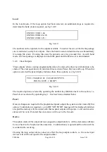
Page 49: ...request the loop number for which the information is required see fig 3 2 14 TUE 15 MAR 21 45 LIST LOOP DEVICES LOOP Fig 3 2 14 The required loop number is entered and accepted upon which the display will initially display the number of devices connected to the loop as shown in fig 3 2 15 TUE 15 MAR 21 45 LIST LOOP DEVICES LOOP 02 96 DEVICES Fig 3 2 15 The number of devices is displayed for a few ...

Page 50: ...es If the printer is enabled the listing will also be hard copied The listing can be aborted using the CANCEL NO key A typical display is shown in fig 3 2 17 ASSEMBLY WORKSHOPS ZONE 12 IONISATION DEVICE 067 LOOP 02 Fig 3 2 17 If no devices are isolated then the NO DEVICES ISOLATED message is displayed for a few seconds before the panel returns to displaying the first option of menu two The listing...

Page 51: ...se LED will still be activated to indicate that the panel has received the call The test mode will automatically carry out a panel reset about twenty five seconds after a test device is activated A further device can now be tested The test fire condition will not cause the internal sounder to go into the continuous mode By the addition of the appropriate output card module an output that is active...

Page 52: ...it is entered an asterisk is displayed see fig 3 3 2 indicating the number of digits already entered All four digits must be entered upon which the panel will check the code validity If this number does not equal the code originally programmed into the panel the INVALID message will be displayed for a few seconds before the PANEL IN ACCESS mode is re entered If the correct password is entered then...

Page 53: ... fire fault or main panel function operation These are stored in no volatile RAM and are therefore retained even in the event of total power down of the panel When full the event log will retain each new event but will loose the oldest This log can be examined by operating the ENTER YES key when the Print of Event Log option is displayed If the printer is enabled the listing will be copied to the ...

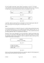
Page 54: ... the device as shown in fig 3 3 7 MAIN ENTRANCE HALLWAY ZONE 01 IONISATION DO1 066 Axxx Fxxx 1 Fig 3 3 7 The bottom line confirms the device parameters indicating zone device type D 01 066 loop device analogue value A and the fire threshold value F When isolated an I will be inserted on the bottom line most right of the display The top line identifies the text message when assigned This display wi...

Page 55: ...tical to the display The listing can be terminated using the CANCEL NO key but no terminated message will be obtained Any fire or fault will automatically terminate the listing 3 3 5 Message Handler Psion only The Message Handler allows both upload and download of the ext messages and message memory clear The option is accepted by operating the EXE key on the Psion Both upload and download are don...

Page 56: ...entered This is done in the normal manner and when a relevant loop is accepted the panel will transfer the display control to the Psion see fig 3 3 12 TUE 15 MAR 21 45 MESSAGE HANDLER REFER TO REMOTE COMPUTER Fig 3 3 12 As described in section 3 1 6 and 3 1 7 connect the Psion and select Cpanel operation The options now available will be displayed on the Psion LCD see fig 3 3 13 Four options are a...

Page 57: ...ch device as it is down loaded When the file is fully loaded the panel will revert to the loop request level and the Psion to the keypad mode A new loop can now be selected upon which display and control is again transferred to the Psion If no temporary file exists the Psion will revert back to its previous level Device 32 Zone 12 Bedroom 10 1st floor Fig 3 3 15 If at the file select stage any oth...

Page 58: ...anel Caution must be exercised when using this option as it does not modify the back up copy file This should be done at the same time using the Edit option When selected the display will indicate the mode and request the device number whose message is required to be modified see fig 3 3 18 Read Single Message Device no Fig 3 3 18 The device number is entered into the Psion and it will then reques...

Page 59: ...temp file is to be saved before being deleted fig 3 3 21 Existing temp file Save before deleting Y or N Fig 3 3 21 The panel will automatically transmit data upon which the Psion will display each message as it is received see fig 3 3 19 The panel will also display the messages as they are transmitted If no data is received within approx two minutes the Psion will revert to the keypad mode Device ...

Page 60: ... accept The LCD VFD will display a request to either ISOLATE or DE ISOLATE as per figs 3 3 25 and 3 3 26 respectively To isolate de isolate press the ENTER YES key If the CANCEL NO key is pressed the display will exit this option and the status of the Auxiliary output left unchanged The panel will indicate EXTERNAL FAULT when AUXILIARY isolated TUE 15 MAR 21 45 ISOLATE AUX OUTPUTS ISOLATE AUX O Ps...

Page 61: ...ram data Psion Range 8 Clear program outputs keypad The required option is displayed using the CANCEL NO key after which it is selected by operating the ENTER YES key 3 4 1 Print Panel Outputs The display options allows the input devices that will activate outputs to be listed on the LCD VFD display and if it is enabled hard copier to the printer When selected the initial display presentation is i...

Page 62: ...ge will be generated As with all other options the occurrence of a fire of fault condition will automatically terminate the listing If allowed to complete the listing a LISTING COMPLETE message is obtained 3 4 2 Print Loop Devices The active listing described above can also be obtained for the loop outputs The listings are separated into two options The first listing gives the output numbers with ...

Page 63: ...CTIVITIES LOOP O P ACTIVE LIST Fig 3 4 5 LOOP 01 DEVICE 012 LOOP 01 DEVICE 034 LOOP 02 DEVICE 024 O P 16 CLEARED ON S LOOP 01 DEVICE 080 LOOP 02 DEVICE 066 O P CLEARED ON R THU 24 NOV 21 45 LOOP O P ACTIVE LIST 3 4 4 Program Panel Outputs The option of sixty four programmable outputs can be provided by the addition of the appropriate output cards to the standard panel These outputs can drive LEDs ...

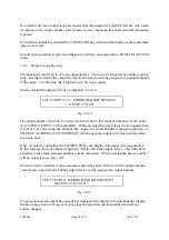
Page 64: ...n the usual manner The display will update and will indicate the active status of the first device on that loop with respect to the selected output see fig 3 4 8 TUE 15 MAR 21 45 PROGRAM PANEL OUTPUTS OUTPUT 12 R L 02 D 001 O Fig 3 4 8 The O indicates that the output will be operated This can be toggled to the active mode by operating any numeric key The O will be replaced by an A and if left in t...

Page 65: ...entered as before but in this mode the number can be from 1 to 128 ONLY FIRST 32 AVAILABLE When accepted the clear status can be toggled from S to R or vice versa using any numeric key Again the S and R indicate the panel function i e SILENCE ALARMS or SYSTEM RESET which cause the output to be cleared after it has been activated Once accepted by operating the ENTER YES key the display will request...

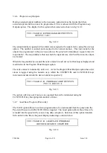
Page 66: ...he active status for each device for that loop is displayed and modified as in the Program Panel Outputs option The active status is indicated by an O or A As for the Program Panel Outputs option the active status is toggled using the numeric keys whilst the ENTER YES and CANCEL NO keys increment and decrement the device number respectively TUE 15 MAR 21 45 PROGRAM LOOP OUTPUTS PUT 2 L 02 D 013 A ...

Page 67: ...ther the temp file or a C file is provided when the Send is selected see fig 3 2 15 If the temp file is selected transmission will occur immediately If a C file is required the selection procedure outlined in section 3 3 5 Send must be carried out When the C file is selected transmission will occur immediately Both the panel and the Psion list the data as it is transmitted Both displays indicate t...

Page 68: ...elected the panel display indicates these three options see fig 3 4 20 TUE 15 MAR 21 45 CLEAR OUTPUTS PANEL 1 DEV 2 LOOP 3 Fig 3 4 20 The required option is selected by operating the number key illustrated next to the section i e Panel clear is selected by operating key 1 Each section is detailed below Panel If major changes are required to the programmed panel outputs the system can be cleared by...

Page 69: ...st the memory is being cleared This clear will not effect the loop devices the outputs will still be assigned to the same loop output devices Note After every programming session the panel must be left for forty seconds in order for new checksums to be calculated If switched off before this time checksum errors will occur at the 4 00am data check If is good practice to obtain a checksum printout a...

Page 70: ... verification checks should be carried out a regular intervals e g daily The checks should be as follows 1 Carry out a buzzer LED and loop test using the LED test option in level one menu as detailed in Section 3 2 7 2 Carry out a system test using the TEST MODE option of the keypad as detailed in Section 3 2 5 ...

Page 71: ...TM0064 Page 71 of 91 Issue 2 01 THIS PAGE IS INTENTIONALLY BLANK ...

Page 72: ... have been approved and must be used for their designated application 1 Detection Loops MICC or Pirelli FP 200 Cable length up to 1 km use 1 5 mm cross sectional area Cable length up to 2 km use 2 5 mm cross sectional area 2 Sounder Circuits Power Supplies Any screened cable approved by the current British Standard for Prolonged operation in a fire Special attention should be made in selection of ...

Page 73: ... European Directive on Electromagnetic Compatibility 89 336 EEC General The preformed knockouts should be carefully removed where required using a small ball pein hammer and the surrounding paint carefully removed to permit a metal to metal contact between the enclosure and cable gland Care must be taken to ensure metal filings do not fall onto the PCBs Metal cable glands must be used for all cabl...

Page 74: ...most every time plastics or textiles are stroked or separated Static charges are collected on adjacent conductors and delivered in the form of sparks passing between the conductors through insulating space or material The sweat layer on the human skin is a sufficient medium to store induced static charges and deliver them to any receptive conductor such as an electronic component or printed circui...

Page 75: ...ir is used for each loop each loop control board being capable of terminating up to two loops It is possible to wire spurs onto a detection loop although full system integrity will be lost as the panel is unable to read the spur in both directions Short circuit isolators should be installed adjacent to the control panel on the feed and return of each detection loop Additional short circuit isolato...

Page 76: ...t is essential that the cable is physically segregated from all components and wiring along it s route to the transformer External Panel Connections All external connections are detailed on the terminal layout which is supplied with the panel Smallest and largest cross sectional area of conductors for terminals ALL PCBs 0 5 to 2 5 mm 240 V a c 1 0 to 2 5 mm 4 7 LOOP WIRING TESTS CAUTION Do not Meg...

Page 77: ... 4 Reconnect the cables in the 28 V output terminals observing the correct polarity of the supply is maintained 4 9 COMMISSIONING 4 9 1 Preliminary Checks Commissioning is to be carried out only after successfully completing the installation of the systems as per the installation instructions Prior to the initial power up of the panel the following procedures must be undertaken 1 Check for any vis...

Page 78: ... allows all of the boards to operate If a fault develops it could seriously affect the operation of the panel therefore if any uncertainty it is recommended to re check the supply as detailed in Section 4 1 7 before continuing The control panel can be powered up 1 Apply the mains to the power unit first 2 Connect the batteries On first powering up the panel the PROCESSOR FAULT LED and the internal...

Page 79: ...s to check the state of the loops and detectors 1 Disconnect the power to the panel 2 Remove the links from the loop 1 terminals on the terminal board and insert the loop connections observing the polarity and 3 Power the panel back up 4 If the yellow fault light on the terminal board remains on after power up switch the panel off and check the loop for continuity to and to Check for a short circu...

Page 80: ...ate and the volt free contacts will change state These can be used for fire brigade signalling All auxiliary outputs can only be switched off once the fire condition is removed by pressing the SYSTEM RESET push button The bell outputs should provide 28 V output when operated This can be stopped by pressing SILENCE ALARMS push button This output can also be activated by pressing the SOUND ALARMS pu...

Page 81: ...gral event printer paper roll is checked weekly 1 Remove dust and dirt from the panel exterior using a soft brush and lint free cloth An approved solvent may be used to remove stubborn dirt build up 2 Examine the exterior for visual signs of damage i e defective or loose cable glands damaged cables etc Rectify any defect 3 Switch the control keyswitch to INHIBIT 4 Disconnect the a c mains supply a...

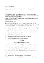
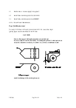
Page 82: ... Maintenance Paper Roll Replacement Use only 57 58 mm 2 25 inch 44 mm for UCP 16 wood free high quality paper maximum diameter roll 50 mm CAUTION Ensure that paper roll replacement is not carried out in areas subject to static electricity Touching the printer s microprocessor or leads connector contacts etc under very adverse conditions could result in damage to the microprocessor ...

Page 83: ...and opposite way to the way it is rolled 7 Bend the paper over the paper guide and insert into the printer correctly centred Put it in as far as it will go 8 Depress the Feed button access through cut out on front panel and check that the paper emerges correctly from the aperture Release Feed button 9 Close the front panel and secure 10 The event printer is now ready for use Ribbon Cartridge Repla...

Page 84: ... the replacement cartridge Tension ribbon if necessary by turning the knurled wheel on the cartridge in the direction indicated on the cartridge 8 Refit the printer front panel and secure with screws 4 Do not overtighten 9 Refit the printer to the front panel and secure with the four screws 10 Refit the printer connector 11 Enable the panel supply 12 Ensure that the paper roll feed is functioning ...

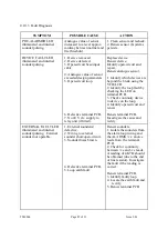
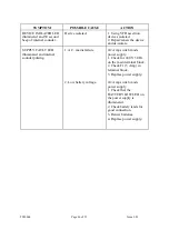
Page 85: ...ich devices are beyond the break using the VFD LCD 2 Identify the loop fault by checking the LED on terminal PCB 3 Check continuity device to device on the loop 4 Identify open circuit and renew Renew terminal PCB Investigate the cause and rectify EXTERNAL FAULT LED illuminated and internal sounder pulsing External sounder not operable 1 External sounder s defective 2 Wiring to external sounder sh...

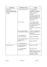
Page 86: ...te SUPPLY FAULT LED illuminated and internal sounder pulsing 1 A C mains failure 2 Low battery voltage 4 2 Amp switch mode power supply 1 Check for 240 V 50 Hz on the main terminal block 2 Check F1 5 Amp in terminal block 3 Replace power supply 4 2 Amp switch mode power supply 1 Check that the BATTERY LOW LED on the power supply is illuminated 2 Check battery leads for good connection 3 Renew batt...

Page 87: ...FIRE LEDs stay on constant 2 Press SYSTEM RESET The VFD should return to STATUS NORMAL The FIRE LEDs should be extinguished 1 Identify the defective device from the VFD 2 Isolate the device using the appropriate menu selection 3 Renew the device and de isolate 1 Check if LOOP FAULT LED on terminal PCB is illuminated 2 Renew PCB if LED is lit Renew terminal PCB Renew processor PCB Renew VFD PCB Con...

Page 88: ...ch day the control panel should be observed for normal operation and any faults should be recorded in the fire log book Weekly In addition to the daily test an automatic detector or break glass unit must be operated to prove the correct operation display and outputs from the control panel It is preferable that a different trigger device is operated each week and records of devices tested should be...

Page 89: ...TM0064 Page 89 of 91 Issue 2 01 THIS PAGE IS INTENTIONALLY BLANK ...

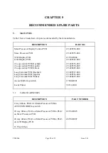
Page 90: ...CB Hochiki Loop Terminal PCB Apollo Loop Terminal PCB Nittan Access Inhibit keyswitch Event Printer 29 020554 000 29 020555 000 43782 D004 29 020543 000 29 020553 000 29 020550 000 29 020605 000 29 020557 000 29 020556 000 29 020625 000 27600 D091 38511 D011 5 1 CABLE HARNESSES DESCRIPTION PART NUMBER 2 way ribbon PLG10 10 Main Processor PCB to ACCESS INHIBIT keyswitch 20 way ribbon PLG6 on Main P...

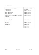
Page 91: ...ol RS422 drive unit PCB comprising four output and one input circuit 8 way Zonal alarm PCB 1 AMP 12 way relay PCB Twin Relay PCB Pulser Timer Network Output 43782 D004 29 020543 000 rev 2 29 020489 000 rev 1 29 020490 000 rev 2 29 020526 000 rev 1 29 000118 000 rev 1 29 000117 000 rev 1 29 000252 000 rev 1 29 020608 000 29 020591 000 29 020592 000 ...

Reviews: