December 2001
06-235793-001
Scorpio
™
4
lease time delay. Abort sequence is dependent upon
programming.
Alarm Condition - Panel Programmed for Two Zone
Mode
Upon receipt of an alarm from one activated detector in
one zone:
•
Red Zone 1 or Zone 2 ALARM LEDs lit.
•
Sounder on.
•
Signal circuit device on for 1 second every 2 seconds.
Upon receipt of an alarm from a second activated detec-
tor in the other zone:
•
Red Zone 1 and Zone 2 ALARM LEDs lit.
•
Sounder on.
•
Signal circuit devices on steady.
•
Programmed release time delay activated.
Upon receipt of an alarm from an activated manual sta-
tion:
•
Red Manual Station ALARM LED lit.
•
Sounder on.
•
Signal circuit devices on steady.
•
Programmed release time delay activated.
Operation of ABORT:
•
Yellow ABORT ACTIVATE LED lit.
•
Discharge is aborted ONLY when alarm is from a de-
tector, and abort is activated during programmed re-
lease time delay. Abort sequence is dependent upon
programming.
Supervisory Condition
Upon receipt of a supervisory signal:
•
YELLOW SUPERVISORY LED lit.
•
Sounder pulses for 1 second every 10 seconds.
Trouble Condition
Upon receipt of a trouble signal:
•
YELLOW TROUBLE LED flashes.
•
Sounder pulses for 1 second every 10 seconds.
All Programming Modes
Operation of SILENCE switch:
•
Yellow SILENCE LED flashes.
•
Sounder off.
•
Signal circuit devices off.
•
A subsequent alarm will turn signal circuit devices on.
RECOMMENDED WIRING COLOR CODE
FOR FIRE SUPPRESSION INSTALLATIONS
Wiring Color Code
Single-Conductor Wires
Black = BK
AC power hot
White = WH
AC neutral
Green = GR
Ground
WIRE SIZES
AC power feed:
#14 minimum (#12 Max.)
All Others:
#14, 16 or 18
BATTERY POWER
Batteries provide 24 hour standby supervision, plus 5
minute alarm load at the end of that time, contingent upon
detection and output limitations stated herein. Panel load-
ing and battery standby comply with NFPA 72. Batteries
must be ordered separately.
Note:
Batteries supplied with control panel should be
placed in service within 3 months of shipment date
if stored at approximately 70°F, or within one
month if stored at 100°F. For longer storage time,
they require charging per manufacturer’s specifi-
cation to prevent permanent loss of capacity.
CAUTION
!
Before servicing batteries, disconnect AC
power. Batteries should be replaced at least
once every 36 months, or as directed by the
local authority having jurisdiction. Do not
install a battery set whose open circuit voltage
is less than 22 volts.
INSTALLATION INSTRUCTIONS
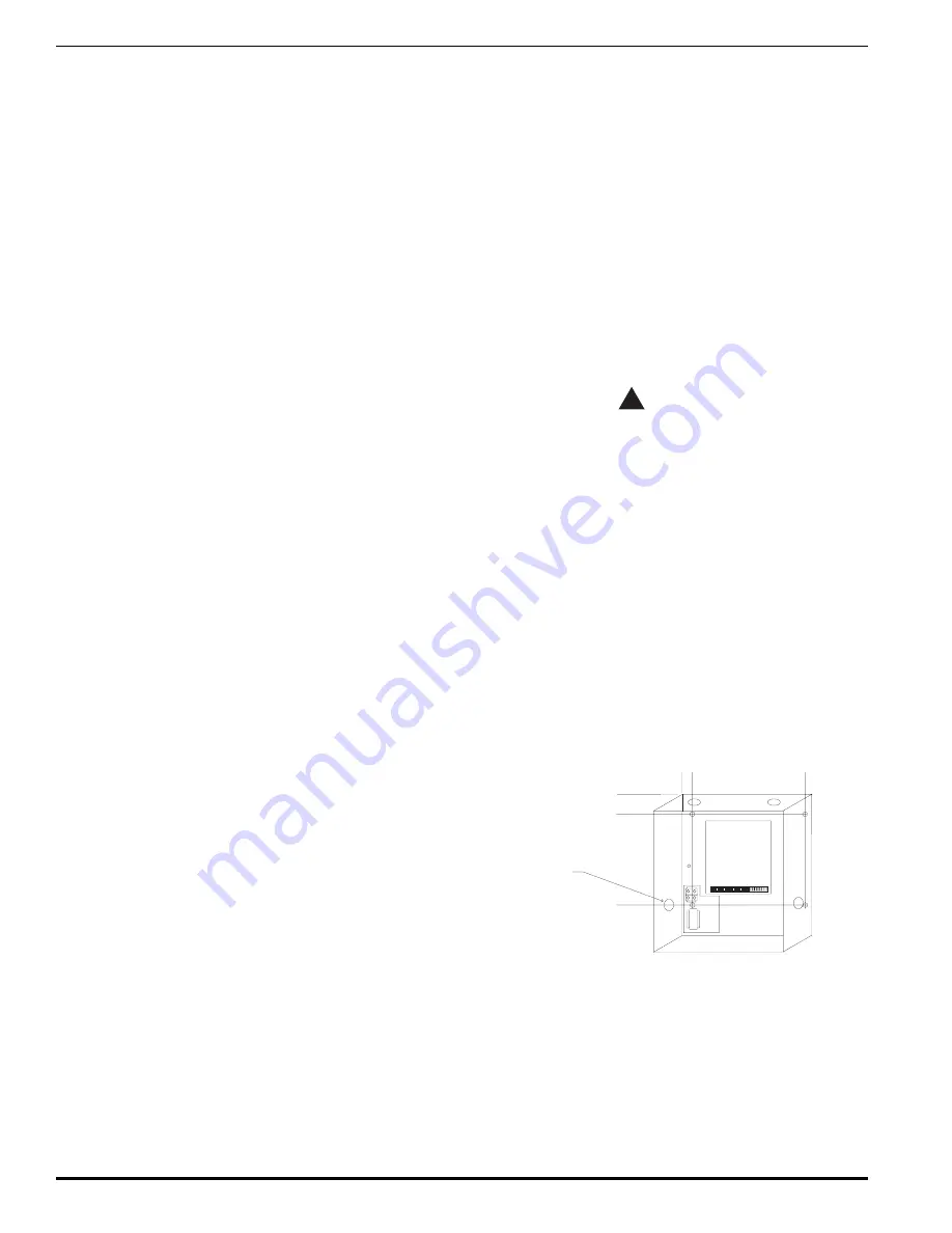
Instructions for mounting (see Figure 2).
All installation wiring shall adhere to NFPA 70 (NEC) and
all State and Local codes.
Position the system in a readily accessible and easily vis-
ible location approximately 4-1/2 feet from the floor. En-
sure that there is a one-foot clearance in front of the system
for the door.
The mounting surface must be flat and in an area that is
relatively clean and dry.
C
D
B
A
A=9.00" C=1.25"
B=1.00" D=8.50"
Enclosure Dimensions
(nominal):
13.25"H x 11.0"W x 2.30"D
AC INPUT
Knockout
G
Figure 2. Mounting Dimensions
1.
Remove knockouts at top and bottom (beware of bat-
tery location on bottom of enclosure) as required.
2.
Insert mounting hardware (not provided) into wall,
spaced to match key holes on back of box.
3.
Mount box on to the screws.
4.
Insert mounting hardware in remaining two holes in
the bottom of the box and tighten all screws.
5.
See installation wiring diagram for further instructions.
firealarmresources.com
Summary of Contents for 151FE1
Page 2: ...firealarmresources com...
Page 15: ...firealarmresources com...


