3-3
November 2002
06-235975-001
Kidde Gemini II System
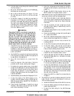
Figure 3-1. Typical Clustered System with Identical Hazards
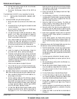
Figure 3-2. Typical Clustered System with Non-Identical Hazards
Discharge Manifold
Agent Piping
LEGEND
Electric Stop Valve
E
Electric Control Head
P
Pneumatic Head
P
P
P
P
P
P
E
E
1st
Cyl.
Last
Cyl.
Additional RHUs
As Needed
Additional
Hazards
R1
R2
SV
R1
R2
SV
R1
R2
SV
R1
R2
SV
MCP Hazard
A
Hazard
A
RHU
#1
Hazard
B
Hazard
B
RHU
#2
Hazard
C
Hazard
C
RHU
#7
Hazard
H
Hazard
H
~
~
~
EOL
EOL
EOL
~
All Hazards
Notes:
1. For clarity, not all RHUs and hazards are illustrated.
2. All unused Release Circuit terminals must be terminated with 2K Ohm resistors as shown in the wiring
diagrams in Appendix E.
3. For details of installation of suppression Systems, please refer to the appropriate Kidde
Suppression System design manual.
Discharge Manifold
Agent Piping
LEGEND
Electric Stop Valve
E
Electric Control Head
P
Pneumatic Head
Directional Check Valve
P
P
E
E
E
E
E
E
1st
Cyl.
Last
Cyl.
Additional RHUs
As Needed
Additional
Hazards
R1
R2
SV
R1
R2
SV
R1
R2
SV
R1
R2
SV
MCP Hazard
A
Hazard
A
RHU
#1
Hazard
B
Hazard
B
RHU
#2
Hazard
C
Hazard
C
RHU
#7
Hazard
H
Hazard
H
~
~
~
~
~
~
Hazard A
E
Hazard B
Hazard C
Hazard H
Notes:
1. For clarity, not all RHUs and hazards are illustrated.
2. All unused Release Circuit terminals must be terminated with 2K Ohm resistors as shown in the wiring
diagrams in Appendix E.
3. For details of installation of suppression Systems, please refer to the appropriate Kidde
Suppression System design manual.
4. Intermediate cylinders may need to be electrically and pneumatically operated.
firealarmresources.com


