4-1
November 2002
06-235975-001
Kidde Gemini II System
CHAPTER 4
SCHEDULED MAINTENANCE
4-1
INTRODUCTION
This chapter contains maintenance instructions for the
Kidde Gemini II System. These procedures should be per-
formed on a scheduled basis. In the event that system prob-
lems are found during the performance of a procedure, see
Chapter 5.
This Chapter contains the following procedures:
•
Walk Test
•
Battery test
•
LCD/LED test
•
Isolation
•
Replacing the battery
4-2
SCHEDULED MAINTENANCE
Maintenance of the system should be performed at a sched-
uled intervals. The interval between maintenance proce-
dures should not exceed any imposed regulations (see
NFPA-72, BS5389 part 1, or other local requirements).
4-3
MAINTENANCE PROCEDURES
The following paragraphs outline general scheduled main-
tenance procedures. The complete procedures should be
performed on an as necessary basis.
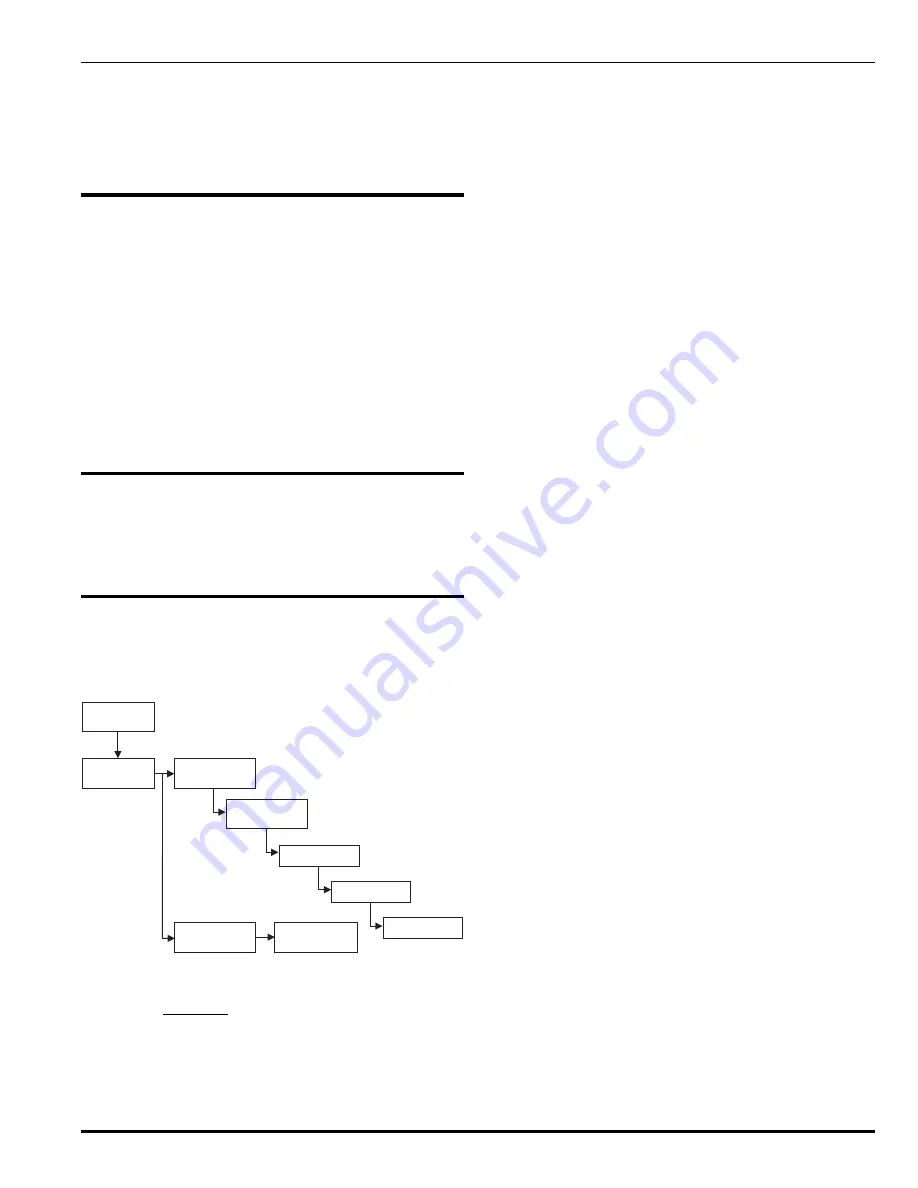
Walk Test
Select unit
for walk test
Select unit
for battery test
Battery Test
Main Menu
Test
Start/stop test
Start/stop test
sounder on/off
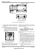
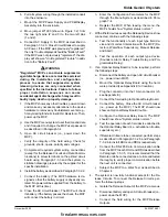
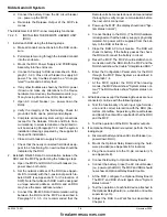
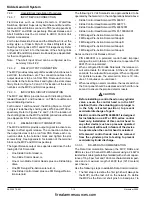
Figure 4-1. Test Menu
4-3.1
Walk Test
The Kidde Gemini II allows service personnel to conduct a
Walk Test on an MCP, RHU and/or an RDU by activating
the input devices connected to it. The system responds to
each activation with a short burst of the programmed sig-
nal circuit. The related signal circuit will only be pulsed if it
has been configured for the Walk Test feature in the soft-
ware configuration.
During the system installation/configuration operation, the
installer would need to enable each signal circuit installed
in the system for Walk Test, if desired. The systems signal
outputs default to Walk Test disabled. When Walk Test is
activated and carried out, the system enters each activa-
tion with a time and date stamp.
The Walk Test feature can only be deactivated through the
user menus.
Note the following:
•
When the Walk Test is active the panel will annunciate
a trouble condition.
•
The Walk Test does not activate the release outputs or
change the primary or programmable relay outputs.
•
If an alarm occurs at another hazard during the Walk
Test, the Walk Test is automatically canceled.
4-3.1.1
PREREQUISITES FOR THE WALK TEST
1.
There are no alarms anywhere in the system
2.
There are no unacknowledged (non-silenced) troubles
anywhere in the system.
3.
No inputs are isolated on the unit being tested. (Indi-
cating circuits and relay outputs may be isolated.)
4-3.1.2
PROCEDURE FOR THE WALK TEST
1.
Press the down arrow to display the Main Menu.
2.
Select Test.
3.
Select Walk Test.
4.
Select the unit to be tested. (Use the up and down ar-
rows to scroll through the units. Then press ACCEPT.)
5.
Select Start.
6.
With the X under the Change field, use the up and down
arrow keys to set the sounder on or off.
7.
Select OK.
8.
In the next display, select OK to start the Walk Test.
Once the Walk Test starts, a Trouble message is gener-
ated, displayed on the panel, and logged in the Event Log.
The Trouble LED lights and the buzzer sounds at that unit
as well as any units programmed in global mode. At the
Main Control Panel the buzzer operates for 1 second every
5 seconds and the Trouble relay is de-energized. If there is
an RDU assigned to the MCP or RHU under Walk Test, its
display will show "In Walk Test."
firealarmresources.com


