P/N 3102475-EN • REV 001 • ISS 09NOV17
3 / 4
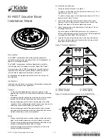
Figure 5: Mounting diagram
Maintenance and testing
Caution:
Equipment damage hazard. To maintain the required agency
listings, do not change factory-applied finishes.
This unit is not serviceable or repairable. Should the unit fail to
operate, contact the supplier for a replacement.
Perform a visual and operational inspection in accordance with
applicable codes and standards or as directed by the local authority
having jurisdiction.
Specifications
Operating voltage
24 VDC or 24 VFWR, nominal
Current
Operating
Supervisory
See Table 1
DC = 1.46 mA, FWR = 2.15 mA
Default settings
Output
level
Output
signal
High dBA
Temporal
Sound level output
ULC
UL
See Table 2
See Table 3
Resonant frequency
3.2 kHz
Audible directional
characteristics
See Table 4
Temporal pattern
0.5 s on, 0.5 s off, 0.5 s on, 0.5 s off, 0.5 s
on, 1.5 s off, repeat cycle
Compatible detectors
All KI and KIR Series detectors
Compatible electrical
boxes
AB4G-SB surface box for audible base;
4 in. square × 2-1/2 in. (64 mm) deep box;
3-1/2 in. octagonal × 2-1/2 in. (64 mm) deep
box; Standard European 100 mm² box
Wire size
12 to 18 AWG (1.0 to 4.0 mm²)
Sizes 16 and 18 AWG (1.0 and 1.5 mm²) are
preferred
Screw torque
Base
mounting
Terminal
18 Ibf-in (2.0 N·m) max.
12 Ibf-in (1.4 N·m) max.
Base diameter
6.8 in. (173 mm)
Base height from box
0.8 in. (21 mm)
Maximum distance
from ceiling (wall
mount)
12 in. (305 mm)
Operating environment
Temperature
Relative
humidity
32 to 120°F (0 to 49°C)
0 to 93% noncondensing
Storage temperature
−
4 to 140°F (
−
20 to 60°C)
Table 1: Operating current in mA (RMS)
Voltage Low
dBA
High
dBA
16 VDC
17
28
24 VDC
24
41
33 VDC
31
52
16 VFWR
41
48
24 VFWR
51
60
33 VFWR
60
66
VDC = Volts direct current, regulated and filtered
VFWR = Volts full wave rectified
Table 2: Sound pressure level per CAN/ULC-S525
Voltage High
dBA
Low
dBA
Reg. 24 VDC
93
89
Reg. 24 VFWR
96
92
Table 3: Sound level output (dBA)
Signal Voltage
Low
dBA
High
dBA
Reverberant room per UL 464 [1]
Steady 16
VDC
75.5 81.7
24 VDC
79.5
84.5
33 VDC
81.8
86.5
Reverberant room per UL 268 and FM [1]
Steady 16
VDC
81.5 87.7
24 VDC
85.5
90.5
33 VDC
87.8
92.5
[1] For UL 464 and UL 268 applications, low dBA settings are for
private mode only
Table 4: Audible directional characteristics [1]
Angle (degrees)
Change in output sound pressure level
90 (ref)
0 dBA
75 and 105
−
3 dBA
65 and 110
−
6 dBA
[1] Measured in a ULC anechoic room. Horizontal and vertical axes
reflect the same pattern.


