background image

 32 

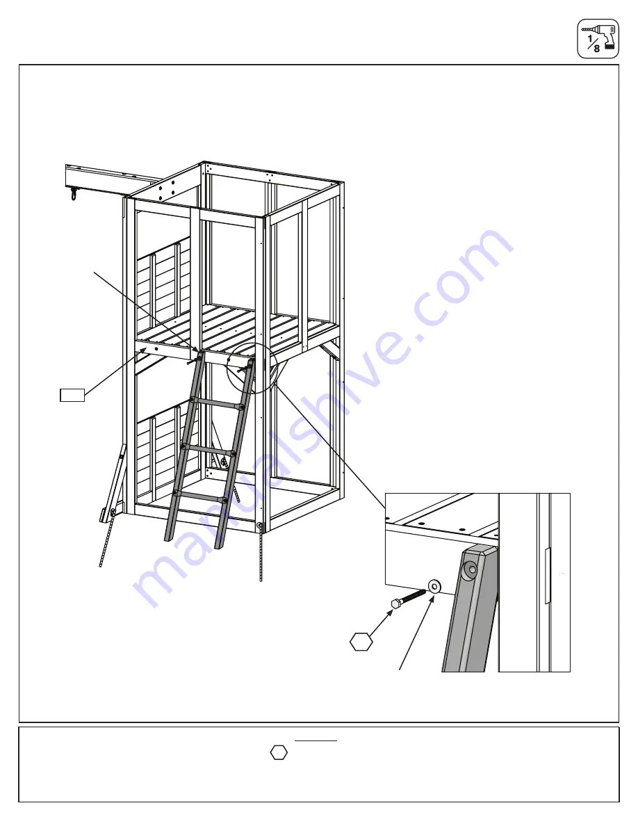
Step 11:  Access Ladder Assembly 

Part 2

D:

  On the Back Wall of the assembly and to the right, place Ladder Assembly against (9273) as shown in fig. 

11.2 making sure that it is flush. Pre-drill holes with a 1/8”(3.2mm) drill bit then attach using 2 (LS3) 1/4 x 3” Lag 

Screw (with flat washer). (fig. 11.3) 

Fig. 11.2

Fig. 11.3

Flush

9273

LS3

Flat Washer

Hardware

2 x 

1/4 x 3” Lag Screw (with flat washer)

LS3

Summary of Contents for BLOOMFIELD F29180

Page 1: ...9180 Table of Contents Warnings and Safe Play Instructions pg 2 Protective Surfacing Guidelines pg 3 Instructions for Proper Maintenance pg 4 About Our Wood Limited Warranty pg 5 Keys to Assembly Succ...

Page 2: ...nd loose ll surfacing materials washing away during heavy rains DO NOT allow children to play on the play set until the assembly is complete and the unit is properly anchored Never add extra length to...

Page 3: ...on the play equipment support posts will help you to see when the material has settled and needs to be raked and or replenished Be sure to rake and evenly redistribute the surfacing in heavily used a...

Page 4: ...constructed of quality materials with your child s safety in mind As with all outdoor products used by children it will weather and wear To maximize the enjoyment safety and life of your Play Set it...

Page 5: ...tment for further assistance Complete and mail registration card to receive important product notifications and assure prompt warranty service 5 Year Limited Warranty KidKraft warrants that this produ...

Page 6: ...identifies information that requires special attention Improper assembly could lead to an unsafe or dangerous condition Where this is shown 2 or 3 people are required to safely complete the step To av...

Page 7: ...GTH CHART inches vs millimetres 6 152 5 140 5 127 4 114 4 102 3 89 3 76 2 64 2 51 1 38 1 32 1 1 8 29 1 25 4 7 8 22 3 4 19 1 2 12 7 1 4 6mm Flat Washer 1 4 6mm Lock Washer 1 4 0 25 6mm Hex Bolt 1 4 6mm...

Page 8: ...8...

Page 9: ...9 9527 34 9 x 63 5 x 1310 5mm Ladder Rail Box 1 3589527...

Page 10: ...Front Wall 1pc 37569271 9327884 Playset Hinge 1pc S0 52933505 Truss Screw 8 x 7 8 1pc 9270 37569270 Behind Wall 1pc 2627 37562627 SW Wall Panel 1pc 9327884 Playset Hinge 1pc S0 52933505 Truss Screw 8...

Page 11: ...2841 15 9 x 108 x 169 3mm Gable Board A Box 2 3582841 8pc 2842 15 9 x 108 x 277 2mm Gable Board B Box 2 3582842 4pc 2843 15 9 x 108 x 304 8mm Gable Board C Box 2 3582843 2pc 2939 25 x 45 x 194 8mm Cu...

Page 12: ...433502 4pc S18 Wood Screw 6 x 1 52013910 16pc S3 Wood Screw 8 x 2 1 2 52043522 115pc S2 Wood Screw 8 x 1 1 2 52043512 8pc S10 Pan Screw 8 x 1 52433510 16pc S11 Wood Screw 8 x 2 52043520 4pc LS1 Lag Sc...

Page 13: ...51103200 28pc S4 Wood Screw 8 x 3 52043530 2pc LS2 Lag Screw 1 4 x 2 1 2 52213222 8pc S33 Wood Screw 8 x 1 52043510 104pc S2 Wood Screw 8 x 1 1 2 52043512 18pc S37 Pan Screw 7 x 5 8 52433009 16pc TS T...

Page 14: ...74 DO NOT SCALE DRAWING 5 4 3 2 1 This drawing is proprietary and confidential All information contained herein is the sole property of Solowave Design Inc Any transmission or reproduction in part or...

Page 15: ...board with Pinch Guard 3330740 Hoop Net and Ball 3330052 Toss Game Add On 3332350 Steel Cupola Mount 9200709 Base Roof Mount Set 3327434 Part Identification Reduced Part Size Part Identification Reduc...

Page 16: ..._ 14459 ___ Box 2 CARTON I D STAMP __ __ __ __ __ 14459 ___ Box 3 MODEL NUMBER F29180 TRACKING NUMBER from ID Plaque B If there are any missing or damaged pieces or you need assistance with assembly p...

Page 17: ...sure the assembly is square then pre drill holes using a 3 16 drill bit and install 4 WL5 1 4 x 2 1 2 Wafer Lags fig 2 1 B Repeat step A to install 4 WL5 1 4 x 2 1 2 Wafer Lags into 9272 Front Panel...

Page 18: ...Back Wall Assembly and 9272 Front Wall Assembly together as shown in figs 2 3 and 2 4 Check to make sure the assembly is square then pre drill pilot holes with a 3 16 drill bit Attach wall assemblies...

Page 19: ...as shown in fig 2 5 and attach 2606 SW Ground to fort using 2 S11 8 x 2 Wood Screws fig 2 5 E Make sure that the 2607 Diagonal is tight to the edge of the SW Wall Panel then pre drill pilot holes with...

Page 20: ...ttach 2608 Floor Joist to each board using the left and centre holes with 2 S4 8 x 3 Wood Screws per board fig 3 1 3 2 3 3 and 3 4 Step 3 Floor Assembly Part 1 1 x Floor Joist 31 8 x 76 2 x 1035 1mm 2...

Page 21: ...ith 2 H11 1 4 x 2 3 4 Hex Bolts with lock washer flat washer and t nut as shown in fig 3 5 Make sure both 2610 Side Joist are level with 2608 Floor Joist Step 3 Floor Assembly Part 2 2610 Wood Parts 4...

Page 22: ...to Front Wall and Back Wall with 4 S3 8 x 2 1 2 Wood Screws per board as shown in fig 3 6 D Tighten all H11 1 4 x 2 3 4 Hex Bolts in both 2610 Side Joist Step 3 Floor Assembly Part 3 8 x 8 x 2 1 2 Woo...

Page 23: ...evenly spaced then attach to 2608 Floor Joist and each 2610 Side Joist with 5 S2 8 x 1 1 2 Wood Screws per board fig 3 7 and 3 8 Step 3 Floor Assembly Part 4 1 x Floor Board 15 9 x 85 7 x 1031 9 mm 8...

Page 24: ...Beam as shown in fig 4 3 IT IS IMPORTANT THAT THIS BOLT IS ATTACHED IT WILL MINIMIZE CHECKING OF WOOD D Attach KidKraft Plaque to centre of 2614 Engineered Beam over top of t nut using 4 S18 6 x 1 Woo...

Page 25: ...and 2615 SW Upright using 3 G4 5 16 x 4 Hex Bolts with lock washer flat washer and t nut Tighten all bolts fig 5 1 C Install 2 WB7 5 16 x 3 Wafer Bolts with flat washer and t nut in the top bolt hole...

Page 26: ...y they are specific for left and right side and attach with 5 G21 5 16 x 3 3 4 Hex Bolts with 2 flat washers and 1 lock nut fig 6 1 and 6 2 Hardware 5 x Hex Bolt flat washer x 2 lock nut Other Parts 2...

Page 27: ...make sure assembly is level then attach from inside the fort assembly into each L Beam Bracket with 4 G27 5 16 x 1 Hex Bolts with 2 flat washers and 1 lock nut fig 7 1 4 x 5 16 x 1 3 4 Hex Bolt flat...

Page 28: ...8 1 Fig 8 2 Fig 8 3 2607 S7 2613 2607 S7 13 330 mm In Ground Rebar Ground Stake Front End Wall End Wall A In the 5 places shown in fig 8 1 drive the Rebar Ground Stakes 13 330mm into the ground again...

Page 29: ...1 x Lower Jamb 31 8 x 76 2 x 1065 2 mm 2601 Wood Parts Hardware 8 x 8 x 7 8 Truss Screw S0 2 x Jamb Mount Other Parts Jamb Mount S0 x 4 per Jamb Mount Centred B In the lower opening of the Front Panel...

Page 30: ...ets so they are flat against the End Wall Panel Attach using 1 S11 8 x 2 Wood Screw Wood and 1 S4 8 x 3 Wood Screw in the upper holes and 1 LS3 1 4 x 3 Lag Screw with flat washer in the lower holes pe...

Page 31: ...s Fig 11 1 Metal Monkey Bar 9527 WL5 FW1 WL5 Other Parts 3 x Metal Monkey Bars 6 x 1 4 x 2 1 2 Wafer Lag flat washer WL5 A Place 2 9527 Ladder Rails side by side with the angled ends facing down as sh...

Page 32: ...place Ladder Assembly against 9273 as shown in fig 11 2 making sure that it is flush Pre drill holes with a 1 8 3 2mm drill bit then attach using 2 LS3 1 4 x 3 Lag Screw with flat washer fig 11 3 Fig...

Page 33: ...11 4 and 11 5 F From inside the Fort measure approximately 3 82 5mm from the bottom of the End Wall Pre drill 2 holes using a 1 8 3 2mm drill bit Install 2 S4 8 x 3 Wood Screws through the 9273 Back W...

Page 34: ...2 8 x 1 1 2 Wood Screw per board fig 12 3 12 4 and 12 5 Fig 12 1 Fig 12 2 Fig 12 3 Fig 12 4 Fig 12 5 2851 2847 Note orientation every other board is flipped One person holds the Rock Support on the in...

Page 35: ...l nut and 1 S10 8 x 1 Pan Screw per rock The Pan Screw is placed in the hole beneath the Pan Bolt fig 12 6 and 12 7 Make sure all hardware is used to secure each rock properly Fig 12 6 Fig 12 7 PB2 Ro...

Page 36: ...nd attach using 2 LS1 x 1 1 2 Lag Screw with flat washers fig 13 1 and 13 2 B On the Back Wall of the assembly and to the center repeat step A to attach second hand grip fig 13 2 and 13 3 Fig 13 2 Fig...

Page 37: ...shown in fig 14 1 pre drill with a 1 8 3 2 mm drill bit then attach slide to fort through the 9272 Front Wall Assembly using 3 S7 12 x 2 Pan Screws fig 14 2 and 14 3 Hardware Other Parts 1 x Slide 3...

Page 38: ...Parts Hardware 8 x 8 x 7 8 Truss Screw S0 2 x Jamb Mount Other Parts Jamb Mount S0 x 4 per Jamb Mount Centred A In the lower opening of the End Panel place 1 2601 Lower Jamb so it measures 17 432mm t...

Page 39: ...llusters as shown in fig 16 4 and attach using 4 S2 8 x 1 1 2 Wood Screws per board fig 16 4 D Repeat to install banister in upper opening on right side of the Back Wall Panel fig 16 3 Fig 16 4 Inside...

Page 40: ...f Support is flush with the bottoms of each Roof End Attach using 2 S4 8 x 3 Wood Screws Fig 17 1 and 17 2 C Repeat step to make 4 assemblies A 2X Roof End Roof Support Build 4 Gable End assemblies Fi...

Page 41: ...a space of 1 25 40mm between the boards and the edge of the gable and attach using 4 S2 8 x 1 1 2 per board fig 17 3 and 17 4 F Repeat steps D and E to complete the remaining 3 Gable Assemblies 2X Gab...

Page 42: ...4 18 5 and 18 6 cetre on each fort face flush 4X 8 x 3 WS PER Gable End flush 4X 8 x 3 WS PER Gable End cetre on each fort face flush 4X 8 x 3 WS PER Gable End cetre on each fort face flush 4X 8 x 3...

Page 43: ...A Bend roof panel along the fold to allow the panel to fit between the gables Fig 19 1 B Place panel onto the gable as shown in fig 19 1 making sure that it s flush to the end and side edge of the 285...

Page 44: ...e assemblies and assemble as shown A note this hole not used make sure Roof End is flush to groove on panel B 3X 8 x 2 WS per roof 2X 8 x 1 1 2 WS per roof other gables hidden for clarity Begin with t...

Page 45: ...fig 19 9 19 10 and 19 11 continue with the other 3 assemblies leaving a 5mm square opening in the centre continue with the other 3 assemblies leaving a 5mm square opening in the centre Continue with t...

Page 46: ...embly install 12 S37 7 x 5 8 Pan Screw as shown in fig 20 3 2X 6 x 5 Tape roof sections together with tape 4 places 2X 6 x 5 Tape roof sections together with tape 4 places Tape roof sections together...

Page 47: ...holes at the top of the Cupola Posts attach 1 2936 Cupola Front Top using 2 TS 6 x 30mm Trim Screws fig 20 4 F Repeat Steps D and E attaching 4 sides together to form the Cupola fig 20 4 and 20 5 6X 6...

Page 48: ...Screw per side fig 20 7 C Place Cupola Roof onto the Cupola Assembly and attach to each Cupola Post using 4 S37 7 x 5 8 Pan Screw as shown in fig 20 8 and 20 9 Bell Steel Cupola Mount 2X 6 x 5 PS 4X...

Page 49: ...panel fits over top of roof flat edge to be tangent to the perpendicular roof panel screw holes in mount block line up to starter holes in roof 4 Places Screw holes in mount block line up to starter...

Page 50: ...Blocks and attach as shown in fig 21 5 using 4 TS 6 x 30mm Trim Screws C Pull string for bell through the square hole in the roof assembly fig 21 6 4X 6 x 30mm Trim Screw Fig 21 5 Fig 21 6 TS Hardware...

Page 51: ...ter the telescope on the 2853 Roof Support and attach using 2 S2 8 x 1 1 2 Wood Screws Fig 22 1 and fig 22 2 x 1 3 4 WS ope 2X 8 x 1 3 4 WS Telescope S2 x 2 Telescope Fig 22 1 Fig 22 2 2853 Hardware 2...

Page 52: ...t the top corners of the Gable Assembly using 2 S10 8 x 1 Pan Screws per flag Fig 23 1 and 23 2 2X Flags 4X 6 x 1 PS 2X Flags 4X 6 x 1 PS 2X 8 x 1 3 4 WS Telescope Fig 23 1 Fig 23 2 Flags x 2 per flag...

Page 53: ...ck Nut 1 x Hoop and Toss Game Add On Hardware Other Parts 3X C B 3X Nu back hoop net back pinch 2X 6 ta mou hard not in in ba Supplie with Loop net all around as shown 3X Cairrage Bolt 3X Nut backplat...

Page 54: ...tall Backboard to Fort using 8 S33 8 x 1 Wood Screws Fig 24 3 24 4 and 24 5 3 25 up oor x 1 1 4 WS mount 3 25 up from floor 8X 8 x 1 1 4 WS 3 25 82 6mm Fig 24 3 Fig 24 4 Fig 24 5 Step 24 Install Baske...

Page 55: ...as shown in fig 24 6 and attach to End Wall using 4 S2 8 x 1 1 2 Wood Screws fig 24 6 Fig 24 6 Step 24 Install Basketball Net Part 3 Hardware 4 x 8 x 1 1 2 Wood Screw S2 2844 9272 S2 S2 1 x Horizonta...

Page 56: ...ey sit on top of the bottom frame and to the inside of the Post and Jamb making sure that all edges are flush Attach 2837 Diagonals using 1 Hex Bolt with flat washer per side and attach each 2838 Leg...

Page 57: ...2 C Place 1 2839 Bottom so that it s centered across the inside of the 2838 Legs Attach using 2 S2 8 x 1 1 2 Wood Screws per side Fig 27 4 2839 2838 S2 Hardware 4 x 8 x 1 1 2 Wood Screw S2 2839 Wood...

Page 58: ...on fits over the leg assemblies Attach top section from the inside using 4 S10 8 x1 Pan Screws and bottom section from the outside using 4 S10 8 x 1 Pan Screws fig 25 5 and 25 6 Fig 25 5 Inside View F...

Page 59: ...Long Belt Swings and Acro Swing to the Swing Hangers Fig 26 1 26 2 Fig 26 1 Fig 26 2 Fig 26 4 Acro Rope Acro Bar Acro Handle Threaded Quick Link Threaded Quick Link Tighten Threaded Link using adjusta...

Page 60: ...rning safety and important contact information A Tracking Number is provided to allow you to get critical information or order replacement parts for this specific model Final Step Attach I D Plaque WA...

Page 61: ...61 NOTES...

Page 62: ...62 NOTES...

Page 63: ...63 NOTES...

Page 64: ...e of assembly Excellent Very Good Average Below Average Poor How would you rate our instructions Excellent Very Good Average Below Average Poor How would you rate the quality of packaging Excellent Ve...

Reviews: